Manual Number: 502-4501 Installation and Operation Manual SmarTrunk II Logic Board for TM Motorola GP68 Portable Radios SmarTrunk Systems, Inc. • ST-865M3 Motorola P/N PMLN4066A 23278 Bernhardt Street • Hayward, CA. 94545 Phone: (510) 887-1950 • Fax: (510) 887-4011 Internet: admin@smartrunk.
Warranty Policy A ll SmarTrunk products are guaranteed to meet or exceed published performance specifications and are warranted against defects in material and workmanship for a period of two (2) years from date of purchase. Third party equipment such as radios, power supplies, antennas, etc., carry the factory warranty of their respective manufacturers. All warranty repairs must be performed at the SmarTrunk factory in Hayward, California, or other factory authorized repair depot.
CONTENTS INTRODUCTION ......................................... V I I 1 OPERATION .............................................. 1 1.1 Landline To Subscriber Call .................... 1 1.2 1.3 Receiving A Call ..................................... 2 Call Routing Codes For Subscriber Initiated Calls ......................................... 2 1.3.1 1.3.2 1.3.3 1.3.4 1.3.5 1.3.6 1.4 Subscriber To Landline Call ................................ 3 Subscriber To Subscriber Call ...........................
Model ST-865M3 SmarTrunk II™ Logic Board 3.2 Installation of the Logic Board ...............18 3.3 Reassemble Radio ................................19 3.3.1 3.3.2 Replace Radio Chassis ....................................... 19 Replace Battery and Antenna ............................ 20 3.4 Trouble Shooting ...................................21 3.5 Portable Radio Programming ...................22 3.5.1 System Tone ..........................................................
CONTENTS Tables Table 1-1 • Call Routing Codes ........................................................ 3 Table 1-2 • Dialing Modes ................................................................ 5 Table 2-1 • ST-852M Programming ............................................... 13 Table 2-2 • Mobile Programming .................................................... 14 Table 4-1 • Programming Options Summary Table .......................... 25 Figures Figure 3-1 • Slide Battery Latch .........................
Model ST-865M3 SmarTrunk II™ Logic Board (This page left blank intentionally) vi
INTRODUCTION T he ST-865M3 SmarTrunk II Logic Board is a microprocessor based radio trunking logic board designed for use with Motorola GP68 Radio. The ST-865M3 implements SmarTrunk II, an efficient radio channel allocation protocol. The SmarTrunk II Logic Board controls all radio functions including channel scan, PTT, and all transmit and receive audio.
Model ST-865M3 SmarTrunk II™ Logic Board (This page left blank intentionally) viii
1 • OPERATION S ubscribers already familiar with the original SmarTrunk system will find the SmarTrunk II digital system just as easy to use. There are also many additional features and enhancements. The ST-865M3 begins trunking operation as soon as the radio is powered on. Channel selection, transmit control, receiver audio, and other radio functions are all under the control of the ST-865M3. Radio channel access is tightly controlled.
Model ST-865M3 SmarTrunk II™ Logic Board 1.2 Receiving A Call The subscriber is alerted to an incoming call by ringing of the subscriber equipment. This alerting takes four forms, related to the type of incoming call. a. A long single high frequency ring is generated by the logic board, then a low frequency dual tone ring is generated by the controller. This indicates an incoming landline call. b.
1 • Operation Table 1-1 Call Routing Codes Routing Code 1 2 3 4 5 9 0 1.3.1 Destination Subscriber to Landline 1 Subscriber to Landline 2 Subscriber to Subscriber Fleet-Dispatch/Group Call Conventional Mode Mobile Operator Emergency Subscriber To Landline Call Routing codes 1 and 2 give the subscriber access to telephone line one or two respectively. A subscriber may be restricted from line 2, or there may not be two telephone lines connected to the ST-852M. In this case, routing code 2 is not valid.
Model ST-865M3 SmarTrunk II™ Logic Board 1.3.5 Mobile Operator Call Routing code 9 calls the subscriber that is preprogrammed as the Mobile Operator. This functions as though the subscriber had used routing code 3 with the subscriber ID number of the Mobile Operator. The Mobile Operator is programmed by the System Operator/Manager. 1.3.6 Emergency Call Routing code 0 causes the ST-852M to access line 1 and dial the preprogrammed emergency phone number.
1 • Operation Table 1-2 and the following paragraphs summarize the advanced dialing modes available: Table 1-2 Dialing Modes Dialing Mode Procedure Store and Send Dialing (number to dial) + (routing code) + * Memory Speed Dialing Programming Speed Dial Memory (The ability to program speed dial numbers can be disabled by the dealer). Redial Mode Priority Call Overide * + (memory location) * (hold until beep) + (memory location) + (number to store) + (routing code) + * 1.4.
Model ST-865M3 SmarTrunk II™ Logic Board 1.4.2 Memory Speed Dialing This procedure is used for dialing a telephone number or subscriber ID number that is stored in the speed dial memory: a. Press the * key. b. Enter the memory speed dial location (0-9). c. Hear a beep followed by the phone system signalling. d. Wait for the called party to answer the call. Example: 1.4.3 To call a telephone number from the speed dial memory location 6, enter the following sequence: * 6.
1 • Operation 1.4.4 Redial Redial is most often used after a telephone number is dialed using the store and send method and the line is busy or a trunking channel is not available. Example: To redial the last number dialed: Press the * key twice. Turning off the power to the radio clears the redial memory. If redial is attempted when no number has been entered, a low frequency error tone will be heard. Redial may be repeated as many times as desired. 1.4.
Model ST-865M3 SmarTrunk II™ Logic Board 1.4.6 Clear Channel Alerting If a call is attempted and no trunking channels are available, the subscriber will get a busy signal. The subscriber can try to redial over and over until the call is processed but this is very frustrating. Clear Channel Alerting Mode eliminates this problem. If Clear Channel Alerting Mode is enabled and all channels are busy when a call is attempted, a busy signal will be generated by the ST-865M3.
1 • Operation 1.6 Radio-Kill If the radio has been remotely disabled by the System Operator/Manager, it will generate a continuous stream of low frequency beeps and will not operate. The radio must be returned to the dealer or System Operator/ Manager for reprogramming. Radio-Kill is a feature that is programmed and managed by the System Operator/Manager.
Model ST-865M3 SmarTrunk II™ Logic Board (This page left blank intentionally) 18
2 • OPERATING MODES T he ST-865M3 may be operated in three modes; Radiotelephone, Fleet Dispatch and Conventional. The System Operator/Manager determines which of these modes are made available to each subscriber. The features of the operating modes are described below: • Radiotelephone - The subscriber receives private calls and group calls. He can initiate telephone calls, call other radiotelephone subscribers and call any group. Call records for each subscriber and group are maintained for billing.
Model ST-865M3 SmarTrunk IITM Logic Board The System Operator/Manager activates a subscriber (individual or group) by programming the ST-852M SmarTrunk II Controller. This activation involves assigning a Subscriber ID Number, Paging Code Number, operational type and a number of other controller parameters. As previously stated, each piece of SmarTrunk II subscriber equipment is capable of "over the air" operation with two Paging Code Numbers.
2 • Operating Modes Example #3: If a subscriber primarily has only radio dispatch/fleet requirements, both the Primary Code and the Secondary Codes may be assigned to group Paging Codes. When programmed in this manner, the equipment will respond to two groups (Group and Sub-Group). The operator of this equipment can only receive Group or Sub-Group calls. An individual user in the subscriber group can make individual outgoing calls to the landline (Primary Code is used).
Model ST-865M3 SmarTrunk IITM Logic Board Table 2-2 Mobile Programming Subscriber Equipment #1 Primary Code Secondary Code 2.2 4100 4100 Subscriber Equipment #2 Subscriber Equipment #3 Subscriber Equipment #4 4101 4103 4102 4104 4103 4104 Conventional If the Conventional Mode feature is enabled, the subscriber may switch to Conventional Mode operation by pressing the 5 key then pressing the (*) key on the keypad (PTT not pressed).
3 INSTALLATION FOR GP68 T he following information is provided to guide the installation of the optional SmarTrunk II Logic Board. Each step is explained in detail and supported with drawings where required. This installation procedure should be followed carefully to avoid damage to the radio and the option equipment. 3.
Model ST-865M3 SmarTrunk II Logic Board 3.1.1 Remove Battery The battery latches are located at the sides of the radio. a. Slide latches away from the front panel on both sides of the radio to unlock battery compartment (Figure 3-1). Figure 3-1 Slide Battery Latch b. Slide battery cover down and away from radio to remove (Figure 3-2).
3 Installation For GP68 3.1.2 Remove Radios Chassis a. Remove the antenna. The antenna screws off counterclockwise (Figure 3-3). b. Remove the two screws at the back of the chassis (Figure 3-3). c. Slide the chassis downwards a little and lift it away from the front housing (Figure 3-3). NOTE Please note that the flat ribbon cable still connects the controller board and the RF board. Be careful not to strain this cable while separating the chassis from the front housing.
Model ST-865M3 SmarTrunk II Logic Board 3.2 Installation of the ST-865M3 Logic Board a. Dismantle the radio by first removing the chassis from the front housing. (Refer to section 3.1 instructions for disassembling the radio). b. Orientate the ST-865M3 Logic Board so that the 12 pin male connector is at the lower edge and facing downwards. (See figure 3-4) c.
3 Installation For GP68 3.3 Reassemble Radio 3.3.1 Replace Radios Chassis a. Slide the chassis upwards to properly fit into the housing and press the bottom of the chassis firmly into place (Figure 3-5). b. Tighten the two screws on the back of the chassis. Figure 3-5 Replace Radios Chassis NOTE Be careful to loop the flex ribbon cable properly when assembling the chassis onto the housing.
Model ST-865M3 SmarTrunk II Logic Board 3.3.2 28 Replace Battery and Antenna a. Replace battery pack by sliding the pack in place. b. Slide battery cover latches towards the front panel to lock. c. Replace the antenna.
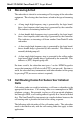
3 Installation For GP68 3.4 Trouble Shooting If the radio does not function correctly, follow the steps in the troubleshooting chart shown in (Figure 3-6).
Model ST-865M3 SmarTrunk II Logic Board 3.5 Portable Radio Programming Program the radio for the SmarTrunk II operating frequencies and the various radio operating parameters required. Refer to the GP68 instruction manual for specific instructions. When the radio programming is complete, the SmarTrunk II Logic Board can be programmed by following the procedure described in Section 4. The most effective method to evaluate proper programming of a radio involves system use.
4 • LOGIC BOARD PROGRAMMING T he ST-865M3 provides the installing technician a flexible programming capability after the ST-865M3 has been installed in the radio. The ST865M3 is programmed by using the keypad on the front of the radio. No special cables or other attachments are required. All programming information is retained in a non volatile EEPROM. To test the installation and programming of the ST-865M3, a functional ST852M with the system ID numbers and paging codes correctly programmed is required.
Model ST-865M3 SmarTrunk II ™ Logic Board Table 4-1 summarizes the programmable features, the keypad sequence for programming, and the default values as provided by the factory. Each feature programmed requires the following steps: a. Enter a two digit programming code. b. Press the # key (indicates end of programming code sequence). c. Enter the data necessary to program that feature. d. Press the # key (indicates end of data sequence).
4 • ST-865M3 Programming Table 4-1 Programming Options Summary Table Feature Programming Sequence Factory Default *Number of Trunking Channels 10# data # 4 *Primary Code 12# data # 0000 *Secondary Code 13# data # 0000 *Priority Subscriber Enable 14# 0# (off) off 14# 1# (on) *Five Digit Access Code 16# data # data # 12345 Return to factory default values 19# *Trunking System ID Number 20# data # 00 *Automatic PTT Mode 21# 0# (off) off 21# 1# (on) *Emergency Call Override 22# 0# (of
Model ST-865M3 SmarTrunk II ™ Logic Board 4.2.2 Primary Code The Primary Code consists of a four digit number that is contained in the SmarTrunk II digital transmission. Any four digit number from 0000 to 9999 may be used. See Section 2 (Operating Modes) before assigning the Primary Code. To program the Primary Code: Enter the program code 12 followed by the # key, then the Primary Code followed by the # key. Example: 4.2.3 To program a unit’s Primary Code to 1234 press: 1 2 # 1 2 3 4 #.
4 • ST-865M3 Programming A priority override is possible only if the subscriber engaging the priority override has a higher priority level than the current subscriber on a channel. There are ten priority levels, from 0 (lowest priority) to 9 (highest priority). The priority level of a SmarTrunk II subscriber is determined by the first digit of the subscriber’s Primary code. For example, a subscriber with a Primary code of 2468 (priority level 2) is currently using a trunking channel.
Model ST-865M3 SmarTrunk II ™ Logic Board The sequence for programming the five digit access code requires the dealer to enter the five digit number two times. This insures that no mistakes are made during the entry of a new access code. To change the five digit access code: Enter the program code 16 followed by the # key, then the new five digit access code followed by the # key. Then enter the five digit access code a second time, followed by the # key.
4 • ST-865M3 Programming To program the ST-865M3 with a trunking system ID number: Enter the program code 20 followed by the # key, and then the trunking system ID number followed by the # key. Example: To program the Trunking System ID Number to 5 press: 2 0 # 5 #. 4.2.8 Automatic PTT Mode The Automatic PTT mode makes radio operation simple for the dispatch operation. With this mode enabled, the subscriber simply presses the PTT switch on the radio to gain channel access.
Model ST-865M3 SmarTrunk II ™ Logic Board 4.2.10 Clear Channel Alerting Mode Clear channel alerting mode notifies the subscriber when a radio channel becomes available. To program the Clear Channel Alerting feature: Enter the program code 24 followed by the # key, and then either 1 (enable) or 0 (disable) followed by the # key. 4.2.11 Example: To enable Clear Channel Alerting press: 2 4 # 1 #.
4 • ST-865M3 Programming 4.2.13 Conventional Operating Mode This program code enables or disables the ability of the radio to operate in conventional mode on non SmarTrunk channels. To program this function: Enter the program code 23 followed by the # key, then enter 0 or 1 followed by the # key. "0" disables the conventional operation capability, "1" enables the capability. Non SmarTrunk channels should be programmed as required using normal radio programming procedures.
Model ST-865M3 SmarTrunk II ™ Logic Board (This page left blank intentionally) 40
APPENDIX A • PROGRAMMING WORKSHEET Programming Sequence Feature Factory Value Default Used *Number of Trunking Channels 10# data # 4 *Primary Code 12# data # 0000 *Secondary Code 13# data # 0000 *Priority Subscriber Enable 14# 0# (off) off 14# 1# (on) *Five Digit Access Code 16# data # data # Return to factory default values 19# 12345 —— *Trunking System ID Number 20# data # 00 *Automatic PTT Mode 21# 0# (off) off 21# 1# (on) *Emergency Call Override 22# 0# (off) off 22# 1# (on) *
Ra Ch dio an ne ls Tr an sm it Re ce ive CT CS S Ra Ch dio an ne ls Tr an sm it Re ce ive CT CS S Model ST-865M3 SmarTrunk™ Logic Board Channel #1 Channel #11 Channel #2 Channel #12 Channel #3 Channel #13 Channel #4 Channel #14 Channel #5 Channel #15 Channel #6 Channel #16 Channel #7 Channel #17 Channel #8 Channel #18 Channel #9 Channel #19 Channel #10 Channel #20 42
APPENDIX B • CROSS REFERENCE CHART Motorola / SmarTrunk Systems Part Number Cross Reference Chart Item Motorola P/N SmarTrunk Systems P/N ST-865M3 Kit (1ea.) ST-865M3 Kit (10ea.
Model ST-865M3 SmarTrunk™ Logic Board Notes: 44