iM1100 Wireless Modem for WindowsTM 95, WindowsTM 98, Windows 2000, and WindowsTM NT User’s Guide @NNTN4180B@ NNTN4180B
CUSTOMER SUPPORT For technical support, contact your service provider. Before you call, make a note of the exact problems and error messages you encountered. NOTE Additional information for iDEN Wireless Data Services can be found on the Motorola iDEN web site at: http://www.mot.
Table of Contents iM1100 Wireless Modem...................................................................................1 iM1100 Wireless Modem Hardware ................................................................1 Data Connectivity ..............................................................................................7 Setting Up Your Modem ...................................................................................8 Using the Modem ......................................................
DECLARATION OF CONFORMITY Per FCC CFR 47 part 2 Section 2.1077(a) Responsible party name: Address: Phone number: Motorola Inc.
iM1100 Wireless Modem iM1100 WIRELESS MODEM Thank you for purchasing the Motorola iM1100 Wireless Modem. The iM1100 Wireless Modem provides you with the capability of performing your most important laptop computer activities, like connecting to the internet or corporate intranets, from outside your office or home. The iM1100 Wireless Modem offers access to the internet over packet data and circuit data networks.
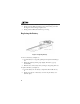
Moving, Removing, and Replacing the Antenna Figure 1. Antenna NOTES To maintain FCC RF exposure compliance, position the antenna and the radio product at least one inch (2.5 cm) from any part of the body of the user or bystanders when using the supplied antenna. When using any approved accessory antenna, position it at least eight inches (20 cm) from any part of any person. Handle the antenna with care. Do not remove it or replace it unnecessarily.
iM1100 Wireless Modem Hardware Removing the antenna enables you to connect an external antenna to your iM1100 Wireless Modem (see “Accessories” on page 41). To replace the antenna: 1. Hold the antenna so that it is pointing straight upward, at a right angle to the bottom of the modem. 2. Snap it back into the antenna opening. Replacing a SIM Card Figure 2. Replacing SIM Card To remove the SIM card (see Figure 2): 1.
1. Turn the unit over, so that the antenna is at the upper right corner. 2. Gently insert the SIM card with the gold contacts facing down and the clipped corner in the upper right corner. 3. Gently push the SIM card in until it stops moving. Replacing the Battery Figure 3. Replacing Battery To remove the battery (see Figure 3): 1. Open the battery door by gently pushing the tab upward and taking it off. 2. Release the battery by lifting it up slightly. The battery pops up automatically. 3.
iM1100 Wireless Modem Hardware Charging the Battery To charge the iM1100 Wireless Modem: 1. With your modem facing up, plug the accessory connector of the Travel Charger (included with your modem) into the charging port on the right side of the modem. 2. Flip open the charger’s’ prongs. 3. Plug the charger into an electrical outlet. The first time you charge the battery, it takes three hours. Subsequent charges take about two and a half hours.
Status Light iM1100 Modem Status Flashing Green In service. Your modem has successfully completed packet data registration. Solid Green Transmitting or receiving data. When Charging Modem Battery (Modem Powered Off) 6 Status Light iM1100 Modem Battery Status Off No battery. Alternating Red and Green Fatal error was detected during power-up: Flashstrap Fatal Error or Invalid Battery. Solid Red Rapid charging. Solid Amber 31%-60% charged. Flashing Green 61%-90% charged.
Data Connectivity DATA CONNECTIVITY Using the iM1100 Wireless Modem enables the following types of data connections: • Packet data: Access the Internet, send and receive e-mail, and transfer small files over the packet data network using standard IP protocols. Packet data transmits packets (blocks) of data at high speed. After the data is transmitted, you can remain connected without being charged for the idle time.
SETTING UP YOUR MODEM The iM1100 Wireless Modem Application and Installation Software enables your iM1100 Wireless Modem to transmit data from your laptop and enables you to control the modem’s functions.
Setting Up Your Modem Preparing the Modem for Setup Before setting up your iM1100 Wireless Modem: • • Charge the battery. See “Charging the Battery” on page 5. Confirm that the SIM card is in place. See “Replacing a SIM Card” on page 3. When to Insert the Modem If you are running Windows NT on your laptop, insert the iM1100 Wireless Modem into the PCMCIA slot before powering up your laptop to start the installation. See “Starting the Software Installation” on page 10.
Starting the Software Installation To begin installing the iM1100 Wireless Modem Application and Installation Software: 1. If you are running Windows NT on your laptop, insert the iM1100 Wireless Modem into the PCMCIA slot. If you are running Windows 95, Windows 98, or Windows 2000, do not insert the modem now; wait to be prompted by the installation software. 2. Turn on your laptop and start Windows 95, Windows 98, Windows 2000, or Windows NT.
Setting Up Your Modem 2. Another window opens. Click OK. Your laptop then restarts. NOTE If you are running Windows 95, you may now see an error message saying that the installation can’t continue. If this happens, follow the steps in “Correcting Resource Conflicts in Windows 95” on page 11. 3. A window opens instructing you to insert the modem. Insert the iM1100 Wireless Modem into the PCMCIA slot in your laptop. 4.
If you see this error message: 1. Click OK to dismiss the error message. 2. Right-click the My Computer icon and select Properties. 3. Choose the Device Manager tab in the System Properties window. 4. Select Modem and click the + to the left of it. This displays a list of modems installed on your laptop. 5. Select Motorola iM1100 PC Card modem.
Setting Up Your Modem 6. Click Properties to verify that this device is causing a resource conflict. This information appears in the Device status area of the Motorola iM1100 PC Card modem Properties window. 7. Click OK to close the Motorola iM1100 PC Card modem Properties window. 8. In the System Properties window, select Motorola iM1100 PC Card modem. Click Remove. This removes the improperly installed iM1100 Wireless Modem from your system. 9.
Continuing the Installation on Windows 2000 You must have administrative rights to install on Windows 2000. 1. When you start the installation software, a window opens instructing you to exit other applications before continue. Exit other applications and click Continue. 2. A window opens instructing you to insert the modem. Insert the iM1100 Wireless Modem into the PCMCIA slot in your laptop. 3. When this window opens, click OK: 4. Restart your laptop. 5.
Setting Up Your Modem Continuing the Installation on Windows NT You must have administrative rights to install on Windows NT. To use the iM1100 Wireless Modem on Windows NT, you must install the iM1100 Wireless Modem on Windows NT and configure Remote Access Service (RAS) for it. RAS enables you to work as though directly connected to a network. 1. When you start the installation software, a window opens instructing you to exit other applications before continue. Exit other applications and click Continue.
5. In the Models area of the Install New Modem window, highlight the Motorola iM1100 Wireless Modem. Then click Next. 6. In the Select Port area of the Install New Modem window, choose an appropriate COM port for the iM1100 Wireless Modem.
Setting Up Your Modem 7. A Modem Setup window opens informing you that you will need to restart your system before you can use the modem. Click OK. 8. The Install New Modem window appears indicating that your modem has been installed successfully. Click Finish.
9. The Network control panel opens. In the Network window, select the Services tab. Within the Services tab, select Remote Access Service. Click Properties 10. The Remote Access Setup window opens. Click Add.. NOTE If a modem is already installed on the same COM port as the i85s phone Wireless Modem, choose an alternate COM port for the i85s phone. Or, if the modem shown occupying the COM port is no longer in use, click Remove to remove it and then click Add.
Setting Up Your Modem 11. The Add RAS Device window opens. Ensure the COM port for your iM1100 Wireless Modem is selected from the drop-down list. Then click OK. 12. The Remote Access Setup window now shows the added COM port. Verify that the iM1100 Wireless Modem was added to the list of RAS devices, verify that TCP/IP is the only dial out network protocol. Then click Continue. 13. In the Network Services Selection window, click Close. 14.
Completing the Installation 1. At this point in the installation procedure, the welcome window has opened. Click Next to continue. 2. The User Information window opens. Enter your name and your company’s name, if it doesn’t automatically display. Then click Next. 3. The Choose Destination Location window opens. Choose a destination location or use the default. Then click Next. 4. In the Select Program Folder window, choose a destination folder, or use the default. Then click Next.
Setting Up Your Modem Setting the Modem Speed After you have completed the installation, make sure that the maximum modem speed is set to 19200. Setting the Modem Speed on Windows 95/98 1. Double-click the My Computer icon on your desktop. 2. Double-click the Dial-Up Networking icon in the My Computer window. 3. In the Dial-Up Networking window, right-click the iM1100 icon and choose Properties. 4. The iM1100 window opens.
5. The Motorola iM1100 PC Card Modem Properties window opens. Make sure that the value shown for Maximum Speed is 19200. If a different value is shown, select 19200 from the drop-down list. 6. Click OK. 7. Click OK again. Setting the Modem Speed on Windows 2000 1. From the Start button, choose Settings > Network and Dial-Up Connections > iM1100. 2. 22 The Connecting iM1100 window opens. Click Properties.
Setting Up Your Modem 3. The iM1100 window opens. Select Motorola iM1100 PC Card Modem from the Connect using: area and click Configure.
4. The Modem Configuration window opens. Make sure that the value shown for Maximum Speed is 19200. If a different value is shown, select 19200 from the drop-down list. 5. Click OK. Setting the Modem Speed on Windows NT 1. Double-click the My Computer icon on your desktop. 2. Double-click the Dial-Up Networking icon in the My Computer window. 3. Select iM1100 from the Phonebook Entry to Dial drop-down list.
Setting Up Your Modem 4. Click More and select Edit entry and modem properties... from the drop-down list. 5. The Edit Phonebook Entry window opens. Choose the Basic tab. In the Dial using: field, select Motorola iM1100 PC Card Modem from the drop-down list. Click Configure. 6. The Modem Configuration window opens. Select a value of 19200 from the Initial speed (bps): drop-down list.Click OK.
7. Click OK again. 8. Click Close. USING THE MODEM Before using the iM1100 Wireless Modem, you must insert it in your laptop’s PCMCIA slot. If the SIM PIN requirement for your modem is enabled, you will be prompted to enter your SIM PIN now. (See “SIM Card Personal Identification Number (PIN)” on page 37.) Powering the Modem On and Off Your modem is automatically powered on when inserted into your laptop’s PCMCIA slot and powered off when removed from the slot.
Using the Modem Registering Your iM1100 Wireless Modem Your iM1100 Wireless Modem must register with your service providers network before you use it. Your modem registers automatically when powered on. The background of the iM1100 Wireless Modem software icon on your taskbar turns green to indicate that your modem is on and registered on the packet data network. Connecting to the Internet via Packet Data To connect the iM1100 Wireless Modem to the internet or an intranet: 1.
Disconnecting from the Internet To disconnect your modem’s connection: 1. If the iM1100 Packet Data Service window is not open, open it by clicking on the iM1100 Wireless Modem icon on your taskbar, or click the desktop icon. 2. Close the window, or do the following: Right-click in the iM1100 Packet Data Service window or choose Mode from the iM1100 Packet Data Service window’s menu bar and then choose Disconnect and Exit. This disconnects your modem from the network and closes the status window.
Using the Modem If You Lose Connection If you lose connection, you will see the following message: To re-establish your connection, click Reconnect. Viewing Text Messages When your modem is connected to the network, you can use it to view and read your Text Messages. To view your Text Messages: • If the iM1100 Packet Data Service window is not open, open it by clicking on the iM1100 Wireless Modem icon on your taskbar, or click the desktop icon.
A window appears displaying your most recent Text Messages. The window’s scroll bars enable you to view more of the message. The buttons near the bottom of the window enable you to read other Text Messages, delete the current Text Message, and close the window: PREV Read previous message. Current message is marked as read. NEXT Read next message. Current message is marked as read. DELETE Delete current message. CANCEL Close window without marking current message as read.
Using the Modem 3. To change the inactivity period, enter a new time. To turn the Inactivation Timer off, uncheck the box. 4. Click Set. Running Applications over Packet Data You can run any standard TCP/IP application during a packet data session. NOTE When a packet-data session is active, any software specifically configured for use with other service providers may need to be reconfigured for use with your service provider.
4. Use this profile to connect. Log in using your ISP user name. 5. Wait for the connection with your ISP to be established. 6. Start your application software (such as, Netscape Navigator or Microsoft Internet Explorer). GETTING STATUS INFORMATION Using the iM1100 Packet Data Connection Window The iM1100 Packet Data Connection window will provide you the following information about your current connection baud rate, duration, bytes received, and bytes sent.
Getting Status Information Using the iM1100 Packet Data Service Window The Packet Data Service window provides modem function information and connection details when connected. To display the iM1100 Packet Data Service window click on the iM1100 Wireless Modem icon.
Status Icons These status icons appear in the body of the iDEN Packet Data Service window: Icon Indicates... 3456 Battery Strength icons — remaining battery charge. More bars on the battery indicate a greater charge. When the modem battery is charging, battery icon displays “sparks” from its top. a Signal Strength icons — strength of the network signal. More bars next to the antenna indicate a stronger signal. Y Packet Data Ready — modem is ready to transmit or receive data.
Getting Status Information • Advanced mode displays technical information about service provider, signal strength, and the number of kilobytes sent and received for the current packet data session. This is mainly used by customer care personnel for troubleshooting purposes. The following additional information is displayed in Advanced Mode and is typically used for troubleshooting: • Carrier No. The hexadecimal equivalent for the service provider number of a cell.
Diagnostics Options Use the Setup options to view and change information about your server. • Check Host enables you to view and change information about your host computer: • The IP host of the IP server you are using. • The ping waiting time, which is the amount of time the modem waits between attempts to contact your server. • The maximum number of times the modem attempts to contact the server before timing out. • The number of bytes per packet of data.
SIM Card Personal Identification Number (PIN) SIM CARD PERSONAL IDENTIFICATION NUMBER (PIN) To prevent unauthorized use of your modem, your SIM card can be protected by enabling the SIM PIN security feature. Each time the modem is powered on, you must enter your SIM PIN. You can change or disable your SIM PIN if desired. The default SIM PIN is 0000. NOTE Incorrectly entering your SIM PIN three times causes the SIM card to be blocked. To unblock your SIM card, you must contact your service provider.
To enable the SIM PIN requirement: 1. Right-click on the iM1100 Wireless Modem icon on your taskbar (see page 26) and choose Properties. 2. The Motorola iM1100 Modem window opens. To enable the SIM PIN requirement, check Enable SIM Card. 3. Enter your SIM PIN and click OK. If you have not changed the SIM PIN, the default SIM PIN is 0000. Changing the SIM PIN To change your SIM PIN: 1. From your Start button, choose Programs > Motorola iM1100 Wireless Modem Applet > Configure program. 2.
SIM Card Personal Identification Number (PIN) To unblock the SIM PIN: 1. From your Start button, choose Programs > Motorola iM1100 Wireless Modem Applet > Configure program. 2. The Modem Configurations window opens. 3. Click User Settings. 4. Click on the SIM PIN Unblock tab. 5. In the SIM PUK: field, enter the 8-digit PUK code given to you by your service provider. 6. Enter a new 4- to 8-digit SIM PIN in the New SIM PIN: field. Enter it again in the Confirm New SIM PIN: field. 7. Click OK. 8.
UNINSTALLING MODEM SOFTWARE You may want to uninstall the iM1100 Wireless Modem Application and Installation Software. If you do this, you will not be able to use your modem until you reinstall the software. NOTE The steps in this procedure may vary slightly depending on your operation system. To uninstall the iM1100 Wireless Modem Application and Installation Software: 1. Begin with the iM1100 Wireless Modem in the PCMCIA slot in your laptop. 2.
Accessories 9. When you restart your laptop, a window opens asking you if you want to remove all components of the iM1100 Wireless Modem Application and Installation Software. Click Yes. NOTE If this window does not appear, you can uninstall the iM1100 Wireless Modem Application and Installation Software by selecting Start > Programs > Motorola iM1100 Wireless Modem Applet > Uninstall the Data Modem Applet. 10. The Remove Shared Files window opens. Click Yes to All. 11. A confirmation window opens.
Safety and General Information IMPORTANT INFORMATION ON SAFE AND EFFICIENT OPERATION. READ THIS INFORMATION BEFORE USING YOUR INTEGRATED MULTI-SERVICE PORTABLE RADIO. RF Operational Characteristics Your radio product contains a radio frequency transmitter to convey the information you wish to send as well as occasional automatic signals used to sustain connection to the wireless network, and a receiver which enables you to receive communication and connection information from the network.
PORTABLE RADIO PRODUCT OPERATION AND EME EXPOSURE To assure optimal radio product performance and make sure human exposure to radio frequency electromagnetic energy is within the guidelines set forth in the above standards, always adhere to the following procedures: Antenna Care Use only the supplied or an approved replacement antenna. Unauthorized antennas, modifications, or attachments could damage the radio product and may violate FCC regulations.
Approved Accessories For a list of approved Motorola accessories, call 1-800-453-0920, visit our website at www.mot.com/iden or look in the accessory section of this manual. THIS RADIO PRODUCT MEETS THE GOVERNMENT’S REQUIREMENTS FOR EXPOSURE TO RADIO WAVES. Your wireless radio product is a radio transmitter and receiver. It is designed and manufactured not to exceed the emission limits for exposure to radiofrequency (RF) energy set by the Federal Communications Commission of the U.S. Government.
Electro Magnetic Interference/Compatibility Electro Magnetic Interference/Compatibility NOTE: Nearly every electronic device is susceptible to electromagnetic interference (EMI) if inadequately shielded, designed or otherwise configured for electromagnetic compatibility. Facilities To avoid electromagnetic interference and/or compatibility conflicts, turn off your radio product in any facility where posted notices instruct you to do so.
Use While Driving Check the laws and regulations on the use of radio products in the area where you drive. Always obey them. When using the radio product while driving, please: • • • 46 Give full attention to driving and to the road. Use hands-free operation, if available. Pull off the road and park if driving conditions so require.
Operational Warnings ! Operational Warnings WARNING For Vehicles with an Air Bag Do not place a portable radio product in the area over the air bag or in the air bag deployment area. Air bags inflate with great force. If a portable radio is placed in the air bag deployment area and the air bag inflates, the radio product may be propelled with great force and cause serious injury to occupants of the vehicle.
! Operational Cautions Caution Antennas Do not use any portable radio product that has a damaged antenna. If a damaged antenna comes into contact with your skin, a minor burn can result. Batteries All batteries can cause property damage and/or bodily injury, such as burns if a conductive material such as jewelry, keys, or beaded chains touches exposed terminals. The conductive material may complete an electrical circuit (short circuit) and become quite hot.
Operational Cautions If the radio product does not work after following the steps listed above, contact your dealer for servicing information. Clean the external surfaces of the radio product with a damp cloth, using a mild solution of dishwashing detergent and water. Some household cleaners may contain chemicals that could seriously damage the radio product. Avoid the use of any petroleum-based solvent cleaners. Also, avoid applying liquids directly on the radio product.
Accessory Safety Information IMPORTANT: SAVE THESE ACCESSORY SAFETY INSTRUCTIONS • Before using any battery or battery charger, read all the instructions for and cautionary markings on (1) the battery, (2) the battery charger, which may include a separate wall-mounted power supply or transformer, and (3) the radio product using the battery. • Do not expose any battery charger to water, rain, or snow as they are designed for indoor or in-vehicle use only.
Accessory Safety Information • • • • • • Do not operate any battery charger if it has received a sharp blow, has been dropped, or has been damaged in any way; take it to a qualified service technician. Do not disassemble a battery charger; take it to a qualified service technician when service or repair is required. Incorrect reassembly may result in a risk of electric shock or fire. Maximum ambient temperature around the power supply or transformer of any battery charger should not exceed 40°C (104°F).
Limited Warranty Motorola Communication Products NOTE: This Warranty applies within the fifty (50) united states and the District of Columbia I. WHAT THIS WARRANTY COVERS AND FOR HOW LONG: MOTOROLA, INC.
Limited Warranty Motorola Communication Products to this warranty unless made in writing and signed by an officer of MOTOROLA. Unless made in a separate agreement between MOTOROLA and the original end user purchaser, MOTOROLA does not warrant the installation, maintenance or service of the Product.
IV. HOW TO GET WARRANTY SERVICE: You must provide proof of purchase (bearing the date of purchase and Product item serial number) in order to receive warranty service and, also, deliver or send the Product item, transportation and insurance prepaid, to an authorized warranty service location. Warranty service will be provided by MOTOROLA through one of its authorized warranty service locations. If you first contact the company which sold you the Product (e.g.
Limited Warranty Motorola Communication Products VI. PATENT AND SOFTWARE PROVISIONS: MOTOROLA will defend, at its own expense, any suit brought against the end user purchaser to the extent that it is based on a claim that the Product or parts infringe a United States patent, and Motorola will pay those costs and damages finally awarded against the end user purchaser in any such suit which are attributable to any such claim, but such defense and payments are conditioned on the following: a.
Limited Warranty Motorola Communication Products (International) NOTE: This Warranty applies in Singapore and the Philippines. I.
Limited Warranty Motorola Communication Products (International) to this warranty unless made in writing and signed by an officer of MOTOROLA. Unless made in a separate agreement between MOTOROLA and the original end user purchaser, MOTOROLA does not warrant the installation, maintenance or service of the Product.
b. Defects or damage from misuse, accident, water, or neglect. c. Defects or damage from improper testing, operation, maintenance, installation, alteration, modification, or adjustment. d. Breakage or damage to antennas unless caused directly by defects in material workmanship. e. A Product subjected to unauthorized Product modifications, disassemblies or repairs (including, without limitation, the audition to the Product of non-MOTOROLA supplied equipment). f.
Limited Warranty Motorola Communication Products (International) that such purchaser will permit MOTOROLA, at its option and expense, either to procure for such purchaser the right to continue using the Product or parts or to replace or modify the same so that it becomes non-infringing or to grant such purchaser a credit for the Product or parts as depreciated and accept its return. The depreciation will be an equal amount per year over the lifetime of the Product or parts as established by MOTOROLA.
Limited Warranty Motorola Communication Products NOTE: This Warranty applies in Canada. I. WHAT THIS WARRANTY COVERS AND FOR HOW LONG: MOTOROLA, INC.
Limited Warranty Motorola Communication Products to this warranty unless made in writing and signed by an officer of MOTOROLA. Unless made in a separate agreement between MOTOROLA and the original end user purchaser, MOTOROLA does not warrant the installation, maintenance or service of the Product.
through one of its authorized warranty service locations. If you first contact the company which sold you the Product (e.g., dealer or communication service provider), it can facilitate your obtaining warranty service. You can also call MOTOROLA at 1-800-453-0920 for warranty service location information. IV. WHAT THIS WARRANTY DOES NOT COVER: a. Defects or damage resulting from use of the Product in other than its normal and customary manner. b. Defects or damage from misuse, accident, water, or neglect.
Limited Warranty Motorola Communication Products the FCC type acceptance labeling in effect for the Product at the time the Product was initially distributed from MOTOROLA. j. Scratches or other cosmetic damage to Product surfaces that does not effect the operation of the Product. k. Normal and customary wear and tear. VI.
MOTOROLA will have no liability with respect to any claim of patent infringement which is based upon the combination of the Product or parts furnished hereunder with software, apparatus or devices not furnished by MOTOROLA, nor will MOTOROLA have any liability for the use of ancillary equipment or software not furnished by MOTOROLA which is attached to or used in connection with the Product or any parts thereof.
Patent and Trademark Information Patent and Trademark Information MOTOROLA, the Stylized M Logo and all other trademarks indicated as such herein are trademarks of Motorola, Inc. ® Reg. U.S. Pat. & Tm. Off. © 2001 Motorola, Inc. All rights reserved. Microsoft and Microsoft Internet Explorer are registered trademarks of Microsoft Corporation. All other product or service names mentioned in this manual are the property of their respective trademark owners.
66