SoftSoft FAX / MODEM USER'S GUIDE Ver 1.
The information in this document is subject to change without notice and does not represent a commitment on the part of the vendor. No warranty of representation, either expressed or implied, is made with respect to the quality, accuracy or fitness for any particular purpose of this document. The manufacturer reserves the right to make changes to the content of this document and/or the products associated with it at any time without obligation to notify any person or organisation of such changes.
The information contained in this manual has been verified at the time of this manual's printing. The manufacturer reserves the right to make any change and improvement in the product described in this manual at any time and without notice. All registered trademarks are the property of their respective owners.Copyright ©1999 All rights reserved. No reproduction of this document in any form is permitted without prior written authorization from the manufacturer. Version 1.
Table of Contents Section One - Introduction 1 1.1 System Requirements ......................................................... 1 1.2 Modem Compatibility ......................................................... 1 Section Two - Installing The Modem 3 2.1 Unpacking Your Modem ..................................................... 3 2.2 Modem Installation ............................................................. 3 2.2.1 Hardware Installation .............................................. 3 2.2.
4.4 Modem experiences errors while online with a remote modem. ............................................................................. 19 4.5 Modem exhibits poor voice record or playback. .............. 19 Section Five - AT Command Set 19 5.1 Executing Commands ....................................................... 21 5.2 Command Format ............................................................. 21 5.3 AT Commands: Basics ...................................................... 21 5.
1 Section One - Introduction Your new 56Kbps modem is a high speed PC communication peripheral that combines Data, Fax, Voice and Speakerphone functions into a single device. This high performance modem connects your computer to all popular modems and fax machines available today. This manual provides installation and operating instructions for your modem. Also included in this manual are listings and descriptions of the standard AT command set, S-registers, and troubleshooting tips.
2 • V.8 Start-up sequence • V.80(Video Ready mode) • V.8 bis Start-up sequence • Plug and Play PCI Spec. V1.
3 Section Two - Installing The Modem This section explains how to connect your modem to your computer. 2.1 Unpacking Your Modem In addition to this manual, your modem package contains the following items: •One modem • Modem software & driver disc •manual include in Disc • One telephone cable NOTE: Contact your dealer if any of the above items are missing from your package. 2.2 Modem Installation The following steps provide instructions for installing your modem. 2.2.
4 7. Replace the computer cover and plug in your computer. Reconnect all cables. 1 2 4 3 5 7 * 8 0 6 9 8. Connect the telephone able into the modem's "LINE" connector (see Figure 2-1). Attach the other end into the telephone wall jack. This completes the internal modem installation. Figure 2-1 NOTE: The back of your modem should look like Figure 2-1. 2.2.2 Setting Up Modem Under Windows This internal modem supports the Plug and Play feature.
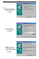
5 select "Search for the best driver for your device" Click "Next" Direct to CD-ROM (ex.
6 Direct to CD-ROM (ex.
7 select "Search for the best driver for your device" Click "Next" Direct to CD-ROM (ex.
8 Click "Finish" 3. Select country (global version is necessary). Selecting a country other than the one in which you are currently located may cause your modem to be configured in a way that violates the telecommunication regulations/laws of that country. In addition, your modem may not function properly if the correct country selection is not made. Only select the country in which you are located. a.
9 b. Click "Advanced" Folder. Select Your country or Region. PART B WINDOWS NT 4.0 Under Windows NT 4.0 a. Please add a new COM PORT into your Windows NT 4.
10 Click "Add...
11 b.
12 Select "Have Disk..." Click "Next" Direct to CD-ROM (eg.
13 C. Please assign this modem on the new COM PORT Click "Next" Click "Finish" 3. Select country (global version is necessary ). Selecting a country other than the one in which you are cu rrently located may cause your modem to be configured in a way that violates the telecommunication regulations/laws of that country. In addition, your modem may not function properly if the correct coutry selection is not made. Only select the country in which you are located. a.
14 b. Click "Advanced " Folder. Select Your Country or Region. 2.2.3 Checking Modem Functionality 1. Start Windows 98 ⇒ Click “Start”⇒ "Settings” ⇒ “Control Panel” ⇒ “Modems”.
15 2. Click “General” and highlight "Motorola SM56 PCI Speakerphone Modem" as shown below. 3. Click "Diagnostic" and highlight the designated COM as shown below. Click “More Info ...” and the system will communicate with the modem.
16 2.2.4 Uninstall Your Modem 1.Click “Start” ⇒ “Settings” ⇒ “Control Panel” ⇒ “Add/Remove Programs" . 2.. highlight "Conexant SoftK56 Modem" 3. click "Add/ Remove" and "OK" to remove the modem.
17 Section Three - Installing and Configuring Communication Software NOTE: Install the communication software according to the software user's manual. Be certain that your software is configured to communicate with the modem on the same COM port and IRQ line used by the modem. You may be prompted by the software to configure certain communication parameters.
18 reading its manual (you may also use any other commercially available communication software). The software manual includes detailed information on all common modem functions.
19 Section Four - Troubleshooting Communication Software Your modem is designed to provide reliable and trouble-free service. Should you experience any difficulty, however, the information contained in this section will assist you in determining and resolving the source of the difficulty. If you cannot resolve your difficulty after reading this chapter, contact your dealer or vendor for assistance. 4.1 Modem does not respond to commands. 1.
20 modem and the communication software. 2. Press the ENTER key several times. The remote system may be waiting to receive your data before it begins. 3. Make sure the correct terminal emulation mode is being used in the software (refer to software manual). 4.4 Modem experiences errors while online with a remote modem. 1. Make sure Call Waiting is turned off. 2. Make sure RTS/CTS hardware flow control is enabled. Do not use XON/XOFF software flow control when transferring binary 3.
21 Section Five - AT Command Set 5.1 Executing Commands Your modem is in Command Mode upon power-on and is ready to receive and execute “AT” commands. The modem remains in Command Mode until it makes a connection with a remote modem. Commands may be sent to the modem from an attached terminal or a PC running a communication program. This modem is designed to operate at common DTE speeds ranging from 115.2Kbps (or 57.6Kbps) to 300bps.
22 to commands), rather than data mode (in which it is transmitting and receiving data). To enter command mode from data mode, enter +++. You need not press the ENTER key. When entering AT commands, the following basic rules apply: l AT commands can be entered in uppercase, lowercase, or mixed text l The characters AT begin all AT commands, except A/ and +++ l The key used as the ENTER key is specified in S-Register S3. l The maximum command length is 64 characters.
23 Command Option E0 E1 H H0 H1 I I0 I1 I2 I3 I4 I5 I6 I7 L M M0 M1 M2 M3 O P Q T O0 O1 O2 O3 P Q0 Q1 T Function Detemines whether the characters you type at the keyboard are displayed (echoed) to the terminal-emulation window (if it is active) or to the communiccations applications.
24 Command V Option V0 V1 X X0 X1 X2 X3 X4 Z Z &C &C0 &C1 &D &D0 &D1 &D2 &D3 &G &G0 &G1 Function Result-Code Format Determines whether the modem sends shortor long- form messages to the communications application, indicating the connection status, rate and mode. Return Numeric Code (Short Form) Return Text (Long Form) Select Call-Progress Result Codes to Return No Carrier; Connect.
25 Command Option &G2 &I &In &I99 &P &P0 &P1 &P2 &R &R0 &R1 &S &S0 &S1 &T &T0 &T1 &TD &TDn &TD99 &V &V0 &V1 &V2 Function 1800 Hz Guard Tone Dial TX Level Level n, n=0 to15, Default =9 Automatic Level Pulse Cycle Used when the modem is instructed to pulse dial.
26 Command %C Option %B3 %B4 %B6 %B7 %B8 %B9 %B11 %B12 %B13 %B14 %B15 %B16 %B17 %B18 %B19 %B20 %B21 %B22 %B23 %B24 %B25 %B26 %B27 %B28 %B29 %B30 %B31 %B32 %B33 %B34 %B35 %B36 %B37 %B38 %B39 %B40 %B41 %B42 %B43 %B44 %B45 %B46 %B47 %B48 Function 2.4 KBPS 4.8 KBPS 9.6 KBPS 7.2 KBPS 12.0 KBPS 14.4 KBPS 16.8 KBPS 19.2 KBPS 21.6 KBPS 24.0 KBPS 26.4 KBPS 28.8 KBPS 31.2 KBPS 33.6 KBPS 32.0 KBPS 34.0 KBPS 36.0 KBPS 38.0 KBPS 40.0 KBPS 42.0 KBPS 44.0 KBPS 46.0 KBPS 48.0 KBPS 50.0 KBPS 52.0 KBPS 54.0 KBPS 56.
27 Command Option %C0 %C1 %D %D0 %Dn %L %L0 %L1 %L2 %L3 %L4 %L7 %L6 %L8 %L9 %L11 %L12 %L13 %L14 %L15 %L16 %L17 %L18 %L19 %L20 %L21 %L22 %L23 %L24 %L25 %L26 %L27 %L28 %L29 %L30 %L31 %L32 %L33 %L34 %L35 %L36 %L37 %L38 %L39 %L40 Function number of bits used to represent data.
28 Command Option %L41 %L42 %L43 %L44 %L45 %L46 %L47 %L48 \K \K1 \K3 \K5 \N \N0 \N1 \N4 \N6 \N7 \Q \Q0 \Q1 \Q3 \T \T0 \Tn \V Function 41333 BPS 42666 BPS 60.
29 Command Option *DD2 *DD3 *DD4 *DD5 *DD6 *DD7 *DD8 *LS *LS0 *LS1 *LS2 *MM *MM0 *MM1 *MM2 *MM4 *MM5 *MM6 *MM10 *MM11 *MM12 *MM13 *MM14 *MM15 *MM16 Function 4 Seconds 6 Seconds 12 Seconds 15 Seconds 20 Seconds 30 Seconds 40 Seconds Low-Speed Operation Protocol Lets you select a communications protocol to communicate with very low-speed or older modems. Bell 103 ITU-T V.21 (international standard) Bell 103 or ITU-T V.21 (Auto determination) Modulation Mode V.34 Auto Modulation V.21 Bell 103 V.
30 Command Option 6 b options: 0 1 5 C options: 00h – FFh, default=00h d options: 0 1 2 +A8T Function Enable computer-controlled V.8 orgination negotiation with +A8x indications Specifies V.8 answer negotiation options Disable Enable computer-controlled V.8 answer negotiation Enable computer-controlled V.8 answer negotiation with +A8x indications Specifies the V.8 CI Signal Call Function Octet options Specifies V.8 control options Disabled Enabled, modem control Enabled, computer control V.
31 Command +DR Option +DR=0 +DR=1 +DS +DS=p,q,r,s p options: 0 1 2 3 q options: 0 1 r options: 512-65535 s options: 6-250 +EB +EB=p,q,r p options: 0 1 2 3 q options: 0 1 r options: 0 1 – 254, default=100 +ER Specifies compression on/off direction No compression Tx direction only Rx direction only Both directions; accept any direction Specifies negotiation Do not disconnect if V.42bis is not negotiated per Direction option Disconnect if V.
32 Command + ESA Option +ES=p,q,r p options: Function Specifies the originate-modem’s Request Error Correction 0 Direct mode 1 Normal mode 2 LAP-M Only 3 LAP-M or MNP 4 MNP Only 6 Initiate Sync Access modem when connection is established q options: Specifies the answer-modem’s Fallback Error Correction 0 EC optional, fallback to Normal mode 1 EC optional, fallback to Direct mode 2 EC required (LAP-M or MNP) 3 EC required (LAP-M only) 4 EC required (MNP only) r options: Specifies the originate-modem’s Fa
33 Command Option f options: 0 +ETBM +ETBM-p,q,r p options: +FCLASS +FLO +FMI? +FMM? +FMR? +FRH +FRM Function modem generates 16-bit CRC on the Reeive direction Specifies Non-Return to Zero (NRZI) options NRZI encoding and decoding are disabled. Disconnect Buffer Delay Control Specifies the disconnect buffer delay with pending transmit data 0 Discard buffered data and disconnect 1 Attempt to transmit until all data is delivered, then disconnect Ignore timer.
34 Command Option ` +FRMm Function Sets the modulation mode for receiving axes Use mode m; see mode options for +FRH, +FTH +FRS +FRSn + FTH +FTM +FTH mode +FTM Wait for Silence Wait (n*10) ms; n=0 to 255 Transmit High-Level Data Link Control (HDLC) mode Use Mode mode; see options for +FRH, above. Transmit Mode Sets the modulation mode for transmitting faxes Use mode mode; see options for +FRH, above.
35 Command Option +GMR? +IFC +IFC=p,q p options: 0 1 2 3 q options: 0 1 2 +ILRR +ILRR=0 +ILRR=1 +ITF +ITF=a,b a options: 0-2047 default=255 b options: Function Display modem-software revision number Flow Control Specifies the computer’s flow control method for data passing to the modem (downstream) None XON/XOFF flow control, no pass-through RTS flow control XON/XOFF flow control, with pass-through Specifies the modem’s flow control method for data passing from the modem (upstream) None XON/XOFF flow con
36 Command Option 300 – 60000 s options: 0 300 – 60000 t options: 0 300 – 60000 u options: 0 300 – 60000 +VCID +VCID=0 +VCID=1 +VCID=? +VDR +VDR=m,n m options: 0 1 n options: 0 1-255 +VEM 0 1-255 +VGT 1-255 +VIP +VLS 0 1 8 9 Function BPS Specifies the maximun data rate in the Tx direction Use the maximum rate of the specified modulation mode BPS Specifies the minimun data rate in the Rx direction Use the minimum rate of the specified modulation mode BPS Specifies the maximum data rate in the Rx direc
37 Command +VNH +VPR +VRA +VRN +VRX +VSD +VSM Option 11 13 Function DCE on-hook, DCE connected to microphone DCE off-hook, DCE conneted to telco, speaker, and microphone (speakerphone) Automatic Hang-up Control +VNH=0 Retain automatic hang-ups +VNH=1 Disable DCE-initiated automatic hang-ups +VNH=2 Disable all Automatic hang-ups Voice DTE-DCE Rate +VPR=0 Autobaud Ringback Gone Timer If, after detecting ringback, no further ringbacks are detected after n/10 seconds, operate as if the remote device ans
38 Command Option +VSM=m,n,p,q m options: 128 129 n options: 8000 P options: 0 q options: 0 +VTD +VTDn +VTS D (f,n) (f,g,n) Examples: +VTX Function Specifies the voice compression parameters Specifies the compression method PCM ADPCM Specifies the sampling rate to determine whether to compress 8000 Hz Parameter p specifies compression and expansion of periods of silence. These parameters are not implemented in Release 1. 0. You may leave them blank or enter the value 0.
39 Section Six - S Register Summary Your modem has 16 registers, designated S0 through S89. Table 6-1 shows the registers, their functions, and their default values. Some registers can have their values changed by commands. If you use a command to change a register value, the command remains in effect until you turn off or reset your modem. Your modem then reverts to the operating characteristics specified in its nonvolatile memory.
40 Section Seven - Event Reporting Word Your can use the AT+VEM command to define events on which to report. The list is encoded as a word composed of the following bits. A 1 in a bit- position indicates an enent is reported. A 0 in a bit- position indicates an enent is not reported. NOTE: Read bits from right to left..