85 Combi, 95 Combi, 105 Combi for Mountfield 2000 and 4000 series 8211-7060-80
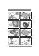
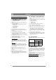
1 125 Combi Pro 2 C B 3 4000 series 4WD, 2000 series A B C 4 A 4000 series 2WD (D) E F G 6 5 H I 7 2 4000 series 4WD 8 4000 series 2WD
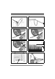
9 2000 series 10 11 17” 12 13 16” 14 1/3 15 16 3
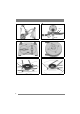
18 17 Q P Q P 45 Nm 20 19 90° 21 22 4000 series 4WD K 2000 series K K K 4
EN ENGLISH 1 GENERAL This symbol indicates WARNING. Serious personal injury and/or damage to property may result if the instructions are not followed carefully. You must read these instructions for use and the machine’s safety instructions carefully. 1.1 Symbols The following symbols appear on the machine. They are there to remind you of the care and attention required in use. This is what the symbols mean: Warning! Read the instruction manual and the safety manual before using the machine.
EN ENGLISH 3 ASSEMBLY 3.1 Assembly on 4WD 4000-series and 2000-series 1. Place the deck in position in front of the machine. 2. Check that the deck mounts are installed on the machine as follows. • Washer (3:D). Only machines up to and including 2006. • Deck mount (3:C). • Washer (3:B). • Circlip (3:A). 3. Screw the arms into each other. See fig. 5. 4. Remove the belt cover (6:H) by loosening the screws 6:I. 5. Set the maximum cutting height. 6.
EN ENGLISH 4 USING THE MACHINE Check that the grass that is to be cut is completely free of foreign objects such as stones etc. 4.1 Cutting height The best cutting results are achieved when the when the top third of the grass is cut off. I.e. 2/3 of the length of the grass remains. See fig. 14. If the grass is long and has to be cut significantly, cut twice using different cutting heights. Do not use the lowest cutting heights if the lawn surface is uneven.
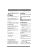
EN ENGLISH 4WD 4000-series: Grip the belt tensioner’s lever with your left hand. Pull the lever and unhook with your right hand. See fig. 7. 2000-series: Unhook the belt idler from the belt. See fig. 9. 7. Loosen the belt guide screws (21, 22:K) a couple of turns and work off the belt from the cutting deck’s pulley. 8. Force the belt off the deck’s pulley. 9. Grip the front edge of the deck and lift up. Lift until the deck is completely vertical and rest the rear edge on the ground. See fig. 17.
ENGLISH EN If the blades are not synchronised, one or more of the following faults may have occurred in the cutting deck: • The positive drive belt has slipped on the gear wheels. • Torque limiting between gear wheels and blade shaft has deployed. The arrows in fig. 20 must be opposite each other for an intact deck. When torque limiting has deployed, the arrows are not opposite each other. • The blade member is incorrectly installed on the blade shaft. Can be installed in three different positions.
Manufactured by GGP Sweden AB