
Instruction manual


6
ENGLISH
EN
3 ASSEMBLY
3.1 Assembly on 4WD 4000-series
and 2000-series
1. Place the deck in position in front of the ma-
chine.
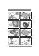
2. Check that the deck mounts are installed on the
machine as follows.
• Washer (3:D). Only machines up to and in-
cluding 2006.
• Deck mount (3:C).
• Washer (3:B).
• Circlip (3:A).
3. Screw the arms into each other. See fig. 5.
4. Remove the belt cover (6:H) by loosening the
screws 6:I.
5. Set the maximum cutting height.
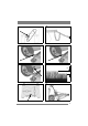
6. Loosen the belt guide screws (21, 22:K) a
couple of turns and work off the belt from the
cutting deck’s pulley.
7. Locate the belt around the machine’s belt pulley
and cutting deck’s pulley.
8. Tighten the belt guide screws (21, 22:K).
9. Tension the belt as follows.
4WD 4000-series
:
Grip the belt tensioner’s lever with your left
hand. Pull the lever and apply the tensioner to
the outside of the belt with your right hand. See
fig.7.
2000-series
:
Tension the belt with the belt idler. The belt
idler should be on the inside of the belt and pull
out to the left (viewed from the driver’s posi-
tion). See fig. 9.
10.Install the belt cover (6:H) with the screws
(6:I).
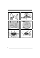
11.Suspend the unit in the implement lifter. See
fig. 10.
12.Perform the basic setting. See 3.4.
13.If the deck has electrical cutting height adjust-
ment, connect the cable to the machine’s front
right socket. See fig. 13.
3.2 Assembly on 2WD 4000-series
1. Place the deck in position in front of the ma-
chine.
2. Check that the deck mounts are installed on the
machine as follows.
• Deck mount (4:G).
• Washer (4:F).
• Lock pin (4:E).
3. Screw the arms into each other. See fig. 5.
4. Set the maximum cutting height.
5. Locate the belt around the machine’s belt pul-
ley.
6. Tension the belt with the belt idler. The belt
idler should be on the left side of the belt
viewed from the driver’s position. See fig. 8.
7. Suspend the unit in the implement lifter. See fig.
10.
8. Perform the basic setting. See 3.4.
9. If the deck has electrical cutting height adjust-
ment, connect the cable to the machine’s front
right socket. See fig. 13.
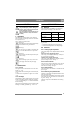
3.3 Tyre pressure
Adjust the tyre pressures according to the table be-
low.
3.4 Basic setting
In order for the cutting deck to cut optimally, the
correct basic setting is required. The deck is in the
basic setting when its rear edge is 5 mm above its
front edge. This means that the deck is inclined
forwards.
Move the deck to the basic setting by lifting and
securing as follows.
On machines with 17” wheels:
Install the washers
and the pins in the top hole. See fig. 11.
On machines with 16” wheels:
Install the washers
and the pins in the middle hole. See fig. 12.
Machine Pressure (bar/psi)
Front Rear
4000-series 0,6/9 0,4/6
2000-series
0,4/6 1,2/17