OPERATION MANUAL CLASSIC 40 and CLASSIC 60 Unit Serial Number Range: 0711XXXX### to Present (From July 2011 to Present) READ THIS MANUAL CAREFULLY FOR INSTRUCTIONS ON CORRECT INSTALLATION AND USAGE, AND READ ALL SAFEGUARDS SECCIÓN EN ESPAÑOL SECTION EN FRANÇAIS AVAILABLE AT WWW.MOVINCOOL.
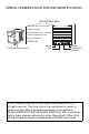
SERIAL NUMBER LOCATION AND IDENTIFICATION Nameplate Label COOLING AMPS. WITH PUMP COMPR. OUTPUT REFRIGERANT/TOTAL CHARGE DESIGN PRESSURE LO/HI PART NO./WEIGHT SERIAL NO. Nameplate Label Position Month Year Model Sequential Number © 2013 DENSO PRODUCTS AND SERVICES AMERICAS, INC. All rights reserved. This book may not be reproduced or copied, in whole or in part, without the written permission of the publisher. DENSO PRODUCTS AND SERVICES AMERICAS, INC.
OPERATION MANUAL CLASSIC 40 and CLASSIC 60
Table of Contents SERIAL NUMBER LOCATION AND IDENTIFICATION ................................... 2 FOREWORD ...................................................................................................... 5 Definition of Terms......................................................................................... 5 GENERAL WARNINGS & CAUTIONS.............................................................. 5 INVENTORY & ASSEMBLY ............................................................................
FOREWORD Congratulations on purchasing the MovinCool spot cooling system. This manual explains how to assemble, install and operate the MovinCool Classic 40, and Classic 60 spot cooling system. Please read this operation manual thoroughly to familiarize yourself with the features of the unit and to ensure years of reliable operation. You may also find it useful to keep this operation manual on hand for reference. Components and/or procedures are subject to change without prior notice.
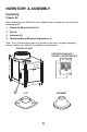
INVENTORY & ASSEMBLY Inventory Classic 40 After unpacking your MovinCool unit, please check to make sure you have the following items: 1. Classic 40 MovinCool Unit (1) 2. Clip (2) 3. Grommet (2) 4. Operation Manual/Product Registration (1) Note: If any of these items were not included in the box or appear damaged, please contact your MovinCool reseller for replacement.
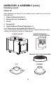
INVENTORY & ASSEMBLY (cont.) Inventory (cont.) Classic 60 After unpacking your MovinCool unit, please check to make sure you have the following items: 1. Classic 60 MovinCool Unit (1) 2. Exhaust Duct for Condenser (1) 3. Clip (2) 4. Grommet (2) 5. Operation Manual/Product Registration (1) Note: Power cord is not supplied with Classic 60. If any of these items were not included in the box or appear damaged, please contact your MovinCool reseller for replacement.
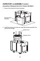
INVENTORY & ASSEMBLY (cont.) Assembly of Exhaust Duct (For Classic 60 ONLY) 1. Remove the exhaust duct from the package. EXHAUST DUCT PACKAGE 2. Install the exhaust duct to the unit, using eight (8) bolts provided in the exhaust duct package.
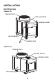
INSTALLATION Unit Overview Classic 40 EXHAUST DUCT COOL AIR OUTLET CONTROL PANEL AIR FILTERS POWER CORD Classic 60 EXHAUST DUCT COOL AIR OUTLET CONTROL PANEL AIR FILTERS 9
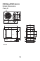
INSTALLATION (cont.) Exterior Dimensions Classic 40 6X 8 10.0 DIA. 0.6 3. 20.7 43.5 25.8 5.1 D IA .1 .0 . 22 DIA 12.9 10.2 5.1 6 M M6 6X 2X 4.3 10.0 23.6 DIA. 20.7 2.3 8.9 30.1 8.9 6.9 5.1 41.3 4xM20 37.8 4.8 2.8 11.8 1.6 Unit: inch 10 1.9 2.8 3.9 1.2 11.8 22.4 25.6 1.
INSTALLATION (cont.) Exterior Dimensions (cont.) Classic 60 8X DIA. 1.0 M6 8.5 31.7 DI A. 13 . M6 8 6x A. DI .2 26 9.3 15.8 22.0 49.4 11.5 6.5 6.5 33.8 6.5 7.1 5.1 DIA. 25.1 3.5 2.4 1.3 4xDIA. 0.5 29.9 7.9 3.1 8.7 Unit: inch 11 10.2 25.2 31.5 7.9 4.3 3.
INSTALLATION (cont.) Choosing an Installation Site CAUTION: Following are some precautions to consider before choosing your installation site. Please review carefully as improper installation may result in personal injury or damage to the unit. 1. Do not use the unit in areas where leakage of flammable gas may occur. 2. Do not use the unit in an environment which contains excessive amounts of corrosive gas or vapor. 3. Do not place obstacles near the air inlet and outlet.
INSTALLATION (cont.) Plugging in the Unit (For Classic 40 ONLY) 1. Check the prongs and surface of the power cord plug for dust/dirt. If dust and/ or dirt are present, wipe off with a clean, dry cloth. 2. Check the power cord, plug and prongs for damage or excess play. If any damage or excess play is found, contact your MovinCool reseller or a qualified technician for repair. WARNING: 1. If the power cord or plug is damaged, repair should only be performed by qualified electrical personnel. 2.
INSTALLATION (cont.) Power Supply and Field Wiring Connection (For Classic 60 ONLY) Power Supply • AC 460 V±10 %, 3 phase and 60 Hz. Do not connect the unit to any other power supply. • The power supply should be a dedicated single outlet circuit with a UL approved short-circuit and ground fault protective breaker with a recommended fuse size of 20 A (20 A maximum). • Securely tighten each terminal.
INSTALLATION (cont.) Power Supply and Field Wiring Connection (For Classic 60 ONLY) (cont.) Power Supply Wires • Use at least 12 AWG for the power wires. Cord type (4 wires): SO, SOT, SOOW or equivalent Voltage rating: 600 V Minimum Heat resistance: 140 °F (60 °C) or above • Prepare three power wires for motive power and one wire (green) for grounding. • Make sure to use conduit tubing when installing power wires. Connection to Classic 60 1.
INSTALLATION (cont.) Optional Accessories and Set Up Configuration Using the optional accessories not only gives you the ability to customize the cooling application, but also makes the unit work more efficiently. Unit Installed on the Floor (For Classic 40 and Classic 60) The unit can be used as a spot cooling system. More information is available at WWW.MOVINCOOL.COM. 1. Standard Configuration Without stand kit (For Classic 40 and Classic 60) CHAMBER DUCT (6 in. DIA.
INSTALLATION (cont.) Optional Accessories and Set Up Configuration (cont.) Unit Installed on the Floor (For Classic 40 and Classic 60) 2. Application Configuration SUSPENSION BAR OR WIRE TEE FLEXIBLE DUCT (12 in. DIA.) “L” FLANGE BLOWOFF DUCT (6 in. DIA.) Note: The maximum length of duct “L” is 66 ft. (20 m). Range of extension static pressure: Classic 40 0.63 IWG (157 Pa) ~ 1.73 IWG (431 Pa) Classic 60 0.57 IWG (142 Pa) ~ 1.
INSTALLATION (cont.) Optional Accessories and Set Up Configuration (cont.) Unit Suspended from the Ceiling (For Classic 40 ONLY) When the unit is suspended from the ceiling, cooling air can be sent from the bottom of the unit. More information is available at WWW.MOVINCOOL.COM. WARNING: Make sure that the ceiling structure is capable of supporting the weigh of the unit, suspension hardware, and the accessories.
INSTALLATION (cont.) Optional Accessories and Set Up Configuration (cont.) Unit Suspended from the Ceiling (For Classic 40 ONLY) 1. Standard Configuration Note: 1. The maximum length of one duct is 6.6 ft. (2 m). Suspend the duct as required with DRAIN HOSE wires or suspension bars. (5/8 in. ID.) 2. When installing the drain pipe, make sure it is angled downward for proper drainage. DUCT 3. Check following items: • No kinks or bends on the (6 in. DIA.) DRAIN PIPE drain hose. • No trap in the drain hose.
INSTALLATION (cont.) Optional Accessories and Set Up Configuration (cont.) Unit Suspended from the Ceiling (For Classic 40 ONLY) 2. Application Configuration DRAIN HOSE (5/8 in. ID.) DRAIN PIPE FLANGE SUSPENSION BAR OR WIRE TEE FLEXIBLE DUCT (12 in. DIA.) “L” BLOWOFF DUCT (6 in. DIA.) TRIM RING Note: The maximum length of duct “L” is 66 ft. (20 m). Range of extension static pressure: 0.63 IWG (157 Pa) ~ 1.
INSTALLATION (cont.) Optional Accessories and Set Up Configuration (cont.) Unit Suspended from the Ceiling (For Classic 40 ONLY) 3. Duct Work Procedure Reverse the blower casing inside the unit. BLIND PLATE UPPER BLOWOFF PORT BLOWER CASING BLIND PLATE RIGHT SIDE PANEL WATER GUARD LOWER BLOWOFF PORT REVERSE BLOWER CASING 180° NUTS POSITIVELY SET THE OPENING OF BLOWER CASING TO LOWER BLOWOFF PORT 1. Remove the right side panel. 2. Remove the water guard located at the lower blowoff port. 3.
INSTALLATION (cont.) Optional Accessories and Set Up Configuration (cont.) Unit Used as a Portable Type The unit can be used as a portable spot cooling system by attaching the wagon kit or caster kit. More information is available at WWW.MOVINCOOL.COM. With wagon kit (For Classic 40 ONLY) DUCT (6 in. DIA.) CHAMBER TRIM RING WAGON KIT With caster kit (For Classic 40 and Classic 60) CHAMBER DUCT (6 in. DIA.) TRIM RING CASTER KIT Note: 1. The maximum length of duct is 6.6 ft. (2 m). 2.
INSTALLATION (cont.) Optional Accessories and Set Up Configuration (cont.) Outdoor Installation of the Unit (For Classic 40 and Classic 60) The unit can be installed outdoors, sending the cool air indoor. More information is available at WWW.MOVINCOOL.COM. SEAL HERE TO PREVENT ENTRY OF RAIN DUCT SUSPENSION WIRE BUILDING WALL DUCT POWER BOX WALL THERMOSTAT WALL THERMOSTAT WIRES RUNNING THROUGH CONDUIT TUBING STAND KIT 7 in. (178 mm) OR HIGHER POWER WIRES RUNNING THROUGH CONDUIT TUBING Note: 1.
INSTALLATION (cont.) Wall Thermostat Connection (Millivolt System ONLY: Option) Connecting Wall Thermostat to Unit 1. Use with a single stage wall thermostat. Thermostat type: Millivolt System 2. Remove three (3) screws from the upper panel on the control panel side and open the upper panel. SCREW (3) 3. Remove two (2) screws and plate from the right side panel. Insert the wire harness through the clip, grommet, and hole in the right side panel.
INSTALLATION (cont.) Wall Thermostat Connection (Millivolt System ONLY: Option) (cont.) Connecting Wall Thermostat to Unit 4. Set the wall thermostat to cooling system mode, since most wall thermostats are designed for both heating and cooling. 5. Prepare the wire harness for connection from the unit to the thermostat. Recommended wire type and size: Thermostat cable / Solid wire 16 ~ 26 AWG 6. Identify the thermostat connectors labeled G, Y, and RC.
INSTALLATION (cont.) Wall Thermostat Connection (Millivolt System ONLY: Option) (cont.) Connecting Wall Thermostat to Unit 8. Install the wall thermostat to the proper location inside the room where it can be conveniently accessed. Do not install the wall thermostat where unusual heating conditions may occur (i.e. hot stove, hot pipe, fireplace, direct sunlight, etc.
INSTALLATION (cont.) Warning Signal Connection (Output Signal Terminal L+ and L-) The controller is equipped with a warning signal output relay type (Form C, normal open dry contact) which can be used to monitor the failure condition. Note: When the unit is configured as suspended from the ceiling, the signal output can be used with alarm speaker or light indicator to monitor proper operation. Relay contactor is closed when the unit operates abnormally.
INSTALLATION (cont.) Warning Signal Connection (Output Signal Terminal L+ and L-) (cont.) Connecting Warning Signal from Controller 3. Insert the warning signal wire through the clip, grommet, and hole in the right side panel. Note: Use recommended warning signal wire size from 16 AWG to 26 AWG for a solid wire, or 16 AWG to 22 AWG for a stranded wire with ring terminal for #6 stud size. 4. Connect the warning device to terminal L+ and L- according to its polarities.
INSTALLATION (cont.) Fire Alarm Control Panel Connection (Input Signal Terminal E+ and E-) The controller is equipped with a normal open input signal connection, which can be connected directly from the fire alarm control panel. This input signal terminal should only be connected to a close or open dry contact signal. When receiving the signal from the fire alarm control panel, the unit turns off and does not turn back on until it has been RESET. Connecting Fire Alarm Control Panel to Controller 1.
INSTALLATION (cont.) Fire Alarm Control Panel Connection (Input Signal Terminal E+ and E-) (cont.) Connecting Fire Alarm Control Panel to Controller 3. Insert the fire alarm signal wire through the clip, grommet, and hole in the right side panel. Note: Use recommended fire alarm signal wire size from 16 AWG to 26 AWG for a solid wire, or 16 AWG to 22 AWG for a stranded wire with ring terminal for #6 stud size. 4. Connect the fire alarm device to terminal E+ and E- according to its polarities.
OPERATION Features 1. A digital electronic control panel, which allows the user to easily control the unit’s operation. 2. Digital LED display that indicates: a. Room temperature and set point temperature (either Fahrenheit or Celsius) b. Status codes 3. The set point temperature can be adjusted between 75 °F (24 °C) and 95 °F (35 °C) by the SET TEMP buttons ( / ). 4. Fire alarm control panel connection with automatic shut off. 5.
OPERATION (cont.) Control Panel Before operating the unit, it is important to familiarize yourself with the basic controls located on the control panel. 1. COOL ON/OFF Button Activates COOL mode or turns the unit off. 2. FAN Button Activates FAN ONLY mode or turns the unit off. 3. SET TEMP Buttons ( / ) Increases or decreases the temperature set point during COOL mode. 4.
OPERATION (cont.) Control Panel (cont.) LED Display Descriptions In normal operation, the LED displays the following descriptions. Display Descriptions Conditions Right decimal point is on. Standby or FAN ONLY mode. Indicates wall thermostat enable function is set. Lit during wall thermostat connection. Indicates room temperature when display is lit. (Left fig. : Room temperature at 78 °F) During COOL mode. Indicates set point temperature when display is flashing for 5 sec. (Left fig.
OPERATION (cont.) Operating Modes The Classic 40 and Classic 60 can be operated in two modes, FAN ONLY and COOL. When in FAN ONLY mode, the unit circulates the surrounding air. When in COOL mode, the compressor is operated and cool air is circulated. 1. COOL Mode Once the compressor has been disengaged for more than 120 sec, the unit operates in FAN ONLY mode for approximately 5 sec before the compressor re-engages. 2.
OPERATION (cont.) Operating in COOL Mode 1. The unit can be operated in COOL mode by pressing the COOL ON/OFF button. Note: In COOL mode the unit can only be turned off by pressing the COOL ON/OFF button. 2. Change the temperature set point by pressing the SET TEMP buttons ( Note: When turning the unit on, the set point and operation mode are determined by the last operating mode. / ). Operating in FAN ONLY Mode 1. The unit can also be operated in FAN ONLY mode by pressing FAN button. 2.
OPERATION (cont.) Self-Diagnostic Codes Self-diagnostic codes are displayed on the control panel under the following conditions. LED Display Codes Condition When room thermistor becomes open or shorted, display shows “E1” and cool mode operation is off. Display and cool mode operation are returned to normal operation after room thermistor is fixed. When freeze thermistor becomes open or shorted, display shows “E2” and cool mode operation is off.
DAILY INSPECTION & MAINTENANCE Clean the Air Filters Clean the air filters once a week. If the unit is used in a dusty environment, more frequent cleaning may be required. A dirty air filter can reduce air output resulting in a decrease in cooling capacity. Filter Removal Method 1. Turn the unit off, by pressing the COOL ON/ OFF button. 2. Remove the air filters. Note: To remove four air filters, lift upward, then pull outward from the bottom. 2 1 1 3. Remove the element from each filter.
DAILY INSPECTION & MAINTENANCE (cont.) In-Season/Off-Season Inspection & Maintenance WARNING: To prevent an accident due to electrical shock, perform inspection and maintenance only after turning off the power at the circuit breaker or unplug the power cord. In-Season 1. Check the prongs and surface of the power cord plug for dust and/or dirt. If dust and/or dirt are present, wipe off with a clean dry cloth. 2. Check the power cord, plug and prongs for damage or excess play.
DAILY INSPECTION & MAINTENANCE (cont.) In-Season/Off-Season Inspection & Maintenance (cont.) Off-Season 1. Operate the unit in FAN ONLY mode for 8 hr. Note: Operation is necessary to dry out the inside of the unit. 2. Disconnect the power cord from the AC outlet. 3. Check the prongs and surface of the power cord plug for dust and/or dirt. If dust and/or dirt are present, wipe off with a clean dry cloth. 4. Check the power cord, plug and prongs for damage or excess play.
TROUBLESHOOTING Check the following items before calling your MovinCool reseller or a qualified technician. CONDITION Unit does not operate POSSIBLE CAUSE REMEDY 1. Power supply is off Check circuit breaker. 2. Incorrect power phase sequence Check connection or exchange two wires of R, S and T. 3. Power interruption Unit will turn on automatically when power returns (Some thermostats require to be reset). 4. Blockage of air duct Check duct for any blockages or excessive kinks in ducting. 5.
TROUBLESHOOTING (cont.) CONDITION POSSIBLE CAUSE Alarm coming Receiving fire alarm signal from unit and unit input stops. REMEDY Check the fire alarm system and confirm that there is no signal input to the unit. The unit returns to the normal operation after the problem is fixed and the controller is RESET or the wall thermostat has been turned off and on. To RESET: Hold down the SET TEMP ( / ) buttons simultaneously for 3 sec.
TROUBLESHOOTING (cont.) Installation Check Sheet ITEMS Installation Unit Check and make sure all screws are tight and unit is secured in place. Check and make sure inlet / outlet air exhaust are clear without blockage. Wiring Check and make sure the unit is properly connected to the dedicated circuit breaker. Check and make sure all wiring are properly connected to R, S and T and secured. Check and make sure ground wire is tighten and secured.
TECHNICAL SPECIFICATIONS ITEMS/FEATURES Rating Conditions Dry bulb Wet bulb Humidity Specifications Power frequency Line voltage Power consumption Current consumption Power factor Starting current Power wiring Classic 40 Classic 60 95 °F(35 °C) 83 °F(28 °C) (60 %RH) 95 °F(35 °C) 83 °F(28 °C) (60 %RH) 60 Hz 3 Phase 220 V 4.20 kw 14.0 A 79 % 72 A 12 (4-core) AWG 25 A 60 Hz 3 Phase 460 V 5.90 kW 8.
TECHNICAL SPECIFICATIONS (cont.) ITEMS/FEATURES Classic 40 Classic 60 Included Included Included Included Included Included Included Included 120 sec Included Included Included Included 120 sec Included Included Included Included 25.8 × 43.5 × 38.0 in (656 × 1,106 × 965 mm) 344 lb (156 kg) 31.7 × 49.4 × 42.
WARRANTY STATEMENT DENSO PRODUCTS AND SERVICES AMERICAS, INC. ("DENSO") warrants its MOVINCOOL Products only to the extent stated in its official written warranties.
P/N: 484007-3621EN Second Issue: April 2013