
User`s manual

NE-4100-P Series User’s Manual Getting Started
3-6
Connecting to the Network
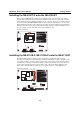
To connect to the network for testing and development purposes, the module should be installed
onto its evaluation board. Make sure that the module is correctly installed onto the evaluation
board, then plug the Ethernet cable into the RJ45 jack. For models NE-4100T-P, NE-4120S-P, and
NE-4120A-P, the RJ45 jack is located on the evaluation board; for models NE-4110S-P and
NE-4110A-P, the RJ45 jack is located on the module itself.
If the cable is properly connected, the RJ45 connector will indicate a valid connection to the
Ethernet as follows:
LAN
The green LED in the upper right corner blinks when the cable is properly
connected to a 100 Mbps Ethernet network, and data is being transmitted.
LAN
The yellow LED in the upper left corner blinks when the cable is properly
connected to a 10 Mbps Ethernet network, and data is being transmitted.
When using a private IP address for the module, which is the factory default, make sure that
netmask and IP settings are configured appropriately in order to access the module from a host on
the network.
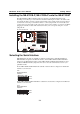
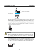
Connecting to a Serial Device
To connect to a serial device for testing and development purposes, the module should be installed
onto its evaluation board. The module’s serial signals are routed to and from the RS-232 COM port
on the evaluation board Use a serial data cable to connect the serial device to the COM port on the
evaluation board.
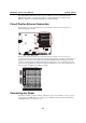
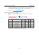
Digital I/O Channel Settings
Each module provides 4 digital I/O (DIO) channels. All 4 DIO channels may be configured by
software for either digital output or digital input mode. A DI channel is a channel that is operating
in digital input mode; a DO channel is a channel that is operating in digital output mode. You may
use the evaluation board’s Digital Output LEDs and Digital Input DIP switches as the digital input
and output devices, or you may connect digital input/output devices to the DI/O Terminal Block.
ATTENTION
When using a digital input device connected to the DI/O Terminal Block, the corresponding
Digital Input DIP switch must be set to “OFF” or “High”. Setting the DIP switch to “ON” or
“Low” will interfere with the signal from your digital input device.