Installation/Operation Manual with Service Replacement Parts Undercounter Dishwashers (with pumped final rinse) Models: 201HT 201HT 201HTN 201LT High temperature w/booster High temperature w/o booster Low temperature chemical sanitizing 401HT 401HTN High temperature w/booster High temperature w/o booster 501HT 501HTN 501LT High temperature w/booster High temperature w/o booster Low temperature chemical sanitizing 401HT Dishwasher serial no. 501HT Issue Date: 3.15.11 www.moyerdiebellimited.
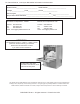
For future reference, record your dishwasher information in the box below.
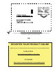
In Canada you can Register by Postage Paid Mail: Cut along the dashed lines, then complete the back of the postage paid card above and mail immediately to validate your machine warranty. OR REGISTER YOUR PRODUCT ONLINE Make sure you are connected to the internet then click or enter the address below. In the U.S.A http://www.moyerdiebel.com/register In Canada http://www.championindustries.
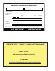
PRODUCT REGISTRATION CARD Serial # Model Date of Installation: Company Name: Address: Telephone #: ( ) --- (Street) Province Postal Code Contact: Installation Company: Address: Telephone #: Contact: FAILURE TO REGISTER YOUR PRODUCT MAY VOID YOUR WARRANTY IMPORTANT IMPORTANT REGISTER YOUR PRODUCT ONLINE Make sure you are connected to the internet then click or enter the address below. In the U.S.A http://www.moyerdiebel.com/register In Canada http://www.championindustries.
Revision History Revision History We reserve the right to make changes to this manual without notice and without incurring any liability by making the changes. Equipment owners may request a revised manual, at no charge, by calling 1 (800) 858-4477 in the USA or by calling 1 (800) 263-5798 in Canada. Revision Date Revised Pages Serial Number Effectivity Revision Description 9.15.06 All W11948 Released first edition 3.22.
Revision History Revision History (continued) Revision Date ii Revised Pages Serial Number Effectivity Revision Description
Blank Page This Page Intentionally Left Blank iii
Limited Warranty LIMITED WARRANTY Moyer Diebel, 3765 Champion Boulevard, Winston-Salem, North Carolina 27105, and P.O. Box 301, 2674 N. Service Road, Jordan Station, Canada, L0R 1S0, warrants machines, and parts, as set out below.
Table of Contents Table of Contents Model 201, 401, 501 Undercounter Dishwashers Revision History ............................................................................................................i Limited Warranty ............................................................................................................ii Model Descriptions ............................................................................................................iv Installation............................
Model Description Model Description 201-HT, 401-HT, and 501-HT Models Pumped final rinse high temperature sanitizing dishwasher with built-in 40°F rise stainless steel electric booster. Single Phase to Three Phase Field Conversion. 201-HTN, 401-HTN, and 501-HTN Models Pumped final rinse high temperature sanitizing dishwasher without built-in 40°F rise stainless steel electric booster.
Installation Receiving NOTE: The installation of your dishwasher must be performed by qualified service personnel. Problems due to improper installation are not covered by the Warranty. 1. Inspect the outside of the dishwasher carton for signs of damage. 2. Remove the carton and inspect the dishwasher for damage. 3. Check for any accessories that may have shipped with your dishwasher. 4. Turn to the front of this manual and follow the instructions to register your machine online. 5.
Installation Electrical Connections For Model 201HT, 401HT, and 501HT machines beginning with S/N 14236 and above 1. Refer to the connection diagrams below. 2. Models 201HTN /LT, 401HTN, 501HTN /LT are equipped with a 4 ft. power cord/plug and only require a 115VAC,15A receptacle. 3. Models 201HT, 401HT, and 501HT 1 PH machines require a 3-wire plus ground supply which includes a current carrying neutral. 4.
Installation Electrical Connections For machines built prior to S/N 14236 WARNING: Electrocution or serious injury may result when working on an energized circuit. Disconnect power at the main breaker or service disconnect switch before working on the circuit. Lock-out and tag the breaker to indicate that work is being performed on the circuit.
Installation Electrical Connections (continued) For Models 201HT, 401HT, and 501HT beginning with S/N 14236 and above WARNING: Electrocution or serious injury may result when working on an energized circuit. Disconnect power at the main breaker or service disconnect switch before working on the circuit. Lock-out and tag the breaker to indicate that work is being performed on the circuit.
Installation Booster Heater Element Field Conversion from Single to Three Phase Operation (continued) Main Terminal Block (MTB) ATTENTION ELECTRICIAN: No power when booster heater is connected for 1 PH The Main Terminal Block (MTB) is a 4-wire connection block which includes a current-carrying neutral. The block can be connected for 3PH or 1PH depending on how the booster heater is wired ( see the previous page).
Installation Water Connections NOTE Plumbing connections must comply with national, local plumbing and sanitary codes. IMPORTANT Make sure that the flexible water supply and drain hoses are not kinked. 1. All models have a 6 ft./1.8m flexible hot water fill hose with a 3/4" female garden hose connector. 2. A 1/2" or larger main incoming supply line should be installed to the dishwasher. 3.
Installation Drain Connections ATTENTION Do not connect the drain hose to a disposer. The dishwasher will not drain correctly. NOTE The dishwasher drains in 8 seconds and drain water exits the hose with considerable force. 1. All models have a 6 ft. 5/8" I.D. drain hose. The maximum drain height connection must not exceed 3 ft.[0.9 m]. 2. The drain hose is located at the rear of the dishwasher. A 5/8" hose-barb fitting is strapped to the drain hose to connect the drain hose. 3.
Initial Start-up Filling the Booster For Models 501HT, 401HT, and 201HT Note: The dishwasher contains a built-in booster heater that was drained prior to shipment and must be filled with water before operating the dishwasher. Booster Fill Switch The booster heater is filled using the Booster Fill Switch. It is located behind the lower front access panel in the center of the bracket that holds the chemical dispensing pumps (see the photos to the right). Fill the booster heater: 1.
Initial Start-up Check List All Models 1. Remove any protective film from dishwasher. 2. Check the interior for foreign material. 3. Make sure the dishwasher is permanently located. 4. Make sure all utility connections are complete. 5. Make sure the flexible drain hose and the hot water fill hose are not kinked. 6. Make sure that the chemical supply containers are full and the chemical pick-up tubes are installed in the proper containers. 7. Make sure the scrap screen is in place. 8.
Initial Start-up Chemical Dispensing Pumps Models 501HT, 501HTN, 401HT, 401HTN, 201HT, 201HTN 1. Models 201HT, 201HTN, 401HT, 401HTN, 501HT, and 501HTN: are equipped with a built-in detergent dispensing pump and a rinse-aid dispensing pump. The pumps are located behind the lower front access panel. Chemical Injection Point Chemical Dispensing Pumps for High Temperature HT and HTN Models. 2. Chemical Pick-up Tubes, stiffener tubes & line strainers.
Initial Start-up Chemical Dispensing Pumps Models 501LT and 201LT ATTENTION (For LT Models Only), 5.25% sodium hypochlorite (chlorine bleach) must be used as a sanitizing agent to provide a minimum concentration of 50 ppm in the final rinse. The 50 ppm concentration must be checked using chlorine test strips to make sure that the proper concentration is maintained 1. Models 501LT and 201LT are equipped with a built-in detergent, rinse-aid, and sanitizer dispensing pumps (See the photograph at right). 2.
Initial Start-up Chemical Dispensers Priming the Chemical Dispensing Pumps Models 501HT, 501HTN, 401HT, 401HTN, 201HT, 201HTN 1. Make sure the chemical containers are full and the correct pick-up tubes are in the containers. 2. Turn the dishwasher power switch ON. The switch will illuminate and the dishwasher will fill with water. 3. Open the dishwasher door, then push and hold the prime push button UP to the DET position until detergent is observed entering the wash tank compartment. 4.
Initial Start-up Chemical Dispensers All Models Note: Chemical Dispensing Pump Speed and Tank Fill Adjustments The chemical dispensing pump speeds are not set at the factory because variations in the type of chemicals supplied by the chemical supplier usually require that the supplier make final the adjustments. 1. Adjustment screws are provided for the dispensing pumps and for the wash tank fill. They are located on the right-side of the dishwasher behind the lower front access panel. 2.
Operation Normal Wash Cycle 501HT Control Panel DET R/A Wash Temperature Digital Display PRIME Prime Switch Final Rinse Temperature Digital Display In-cycle Light Scrub In-cycle Light Scrub Push button Start Push button ON/OFF Power Switch 1. Push the POWER switch up to the ON position. The switch illuminates, water enters the wash compartment. The booster heater begins to heat the final rinse water then the wash tank heater heats the wash tank water. 2.
Operation Normal Wash Cycle (continued) 6. Check the rinse cycle temperature gauge during the final rinse cycle to ensure the final rinse temperature ranges between 180-195°F/82-91°C for high temperature models. NOTE: Model 201 Model 401 Prior to S/N W100120006 Combination Wash / Rinse Temperature Gauge Models 201 and Models 401, (prior to S/N W10012006 for Model 401), have a single temperature gauge to indicate the wash and rinse water temperatures.
Operation Dishwasher Drain Operation 1. Push the dishwasher POWER switch up to the ON position. 2. The POWER switch illuminates and the machine fills with water. 3. Press and hold the green START button for 1 second. (Silver button for Model 501HT). 4. Release the START switch. 5. The dishwasher starts and the green cycle light illuminates. 6. Check the temperature gauge to confirm that it displays the correct incoming hot water temperature.
Cleaning The best preventative maintenance is keeping the dishwasher as clean as possible during regular use. A regular cleaning schedule will increase the life of the dishwasher and ensure the best results. Cleaning CAUTION: Damage to the unit or improper operation may occur if components are not flushed and cleaned on a regularly scheduled basis. Daily-End of the Day 1. Push the POWER switch to the OFF/DRAIN position and close the door to drain the tank.
Cleaning Cleaning Daily-End of the Day (continued) 6. Reinstall the scrap screen. 7. Wipe the exterior of the dishwasher clean using a soft cloth and mild detergent. 8. Leave the dishwasher door open overnight to allow the inside to dry.
Cleaning Cleaning After Meal Period or Every 8 Hours Clean the scrap screen after each meal period and more frequently if necessary in order to keep the scrap screen from becoming clogged. Your dishwasher should be de-limed regularly. The frequency will depend on the mineral content of your water. De-liming Inspect your machine interior for lime deposits. If de-liming is required, a de-liming agent can be used to remove the deposits.
Maintenance Maintenance Schedule The best maintenance you can perform is to keep your dishwasher clean. Before and During Operation - Check the temperature gauges during operation to ensure the proper temperatures are maintained. - Check the chemical supply container level and replenish if necessary. Weekly Maintenance 1. Inspect all water lines for leaks. 2. Check drain for leaks. 3. Clean accumulated lime deposits from the heating element. 4. Inspect each spray arm for clogged nozzles. 5.
Troubleshooting Condition Cause Solution Dishwasher will not run. Door not closed. Main power OFF. Dishwasher OFF. Close door completely. Check breaker on panel. Turn dishwasher ON. Low or no water. Main water supply off. Solenoid valve defective. Solenoid strainer clogged. Flow washer defective. Timer board defective. Open supply valve. Install repair kit or replace. Clean strainer. Replace flow washer. Test/replace timer board. Chemicals won’t feed into dishwasher. Chemical supply low.
Blank Page This Page Intentionally Left Blank 22
Service Replacement Parts Service Replacement Parts Illustration Pg. Wash Pump/Motor Assy - All Models........................................................... 24 Wash Tank, Drain, Scrap Screens - All Models........................................... 26 Built-in Electric Booster (201HT, 401HT, 501HT)........................................ 28 Base Electrical Components - All Models.................................................... 30 Fill Piping - All Models...................................
Wash Pump/Motor Assy - All Models 12 10 11 13 9 7 3 8 5 4 6 2 1 24
All Models - Wash Pump/Motor Assy Item No. Part No. Description Qty. 1 2 3 4 5 6 7 8 9 0512340 0512341 114144 0501501 0501478 0512345 114139 110285 114137 SCREW, M4.0x0.
Wash Tank, Drain, Scrap Screens - All Models Model 401 Only P/N Description 2 Qty 110750 Gasket 110855 Plug 1/4" Plastic 110856 Nut 1/4" Plastic 2 2 2 18 Item 4 not used on Model 401 4 26 25 Model 401 Only P/N 3 29 Description 109034 Gasket 108418 Plug 1/2" Plastic 108417 Nut 1/2" Plastic 24 Qty 1 1 1 5 22 23 28 29 20 6 26 7 21 Item 6 & 26 not used on Model 401 8 9 11 10 19 12 13 14 17 16 15 26
All Models - Wash Tank, Drain, Scrap Screens Item No. Part No. Description Qty. 1 0509302 94” DRAIN HOSE - 5/8” ID X 1” OD N/S 1 2 0712136 SCREEN, SCRAP ASSY 1 3 0512107 THERMOMETER, 7 FT. CAPILLARY (Except 501HT) 1 4 0512169 HEATER, 120VAC 750W (For Low Temp.
Built-in Electric Booster (201HT, 401HT, 501HT) 401 HT Only 15 14 22 14 13 14 15 12 23 11 24 10 21 1 8 2 3 15 4 14 5 16 6 7 17 18 14 13 19 12 20 15 28
Built-in Electric Booster (201HT, 401HT, 501HT) Item No. Part No. Description Qty. 1 2 3 4 0509042 0512185 0508817 109985 BOOSTER TANK BOLT, HEX FLANGE 1/4-20 X 3/8 SS PLUG, 1/8 HEX COUNTERSUNK SEAL, ELECTRIC HEATER FLANGE 1 2 1 1 5 111235 HEATER 5/6.6KW 208/240V 1 111233 HEATER 7.
Base Electrical Components - All Models For Booster Heater (Beginning with S/N 14236 and above) 1 9 R IN S 2 5 For Wash Tank Heater (All S/N’s) E B O O SST W E IT R C F H - IL L + W A S H 3 F I O L -F O L FN For Booster Heater (Prior to S/N 14236) 8 1 7 201HT, 401HT, 501HT 4 6 5 4 2 For Wash Tank Heater (All S/N’s) 201LT, 501LT 8 10 30
All Models - Base Electrical Components Item No. Part No. Description Qty.
Fill Piping - All Models 32
All Models - Fill Piping Item No. 1 2 3 4 5 6 7 8 9 Part No. 0502653 0512185 0300065 0300203 0502618 0503679 0509526 0505320 0504952 Description ELBOW, 90 DEGR 3/8MPTX1/2 HOSE BOLT, HEX FLANGE 1/4-20 X 3/8 SS SUPPORT, VALVE CLAMP, VALVE HOSE BARB, 1/2 X 3/8 MPT CLAMP, SS GEAR-MIN. 5/16-MAX.7/8 HOSE, 1/2 X 7FT FEM.GARD.ADAPT. WASHER, 1” O.D. GARDEN HOSE VALVE, FILL 5.0 GPM (Breakdown on next page) Qty.
Fill Valve Assy - All Models 9 8 7 6 5 34
All Models - Fill Valve Assy. Item No. Part No. Description Qty. 1 0504952 SOLENOID VALVE, COMPLETE (5.0 GPM) 1 2 0502803 STRAINER SCREEN, SOLENOID VALVE 1 3 0502804 WASHER, SEAL 1 4 0504958 WASHER, FLOW 5.
Fill Chute Assy - All Models 1 8 FROM TOP OF BOOSTER OR FILL VALVE 9 7 6 2 3 36 5 4 FROM DETERGENT PUMP FROM RINSE-AID AND SANITIZER PUMPS
All Models - Fill Chute Assy. Item No. Part No. Description Qty. 1 106090 TIE PLATE 2 2 0509048 GASKET, INLET CHUTE 1 3 0508867 CHUTE, INLET INJ.MOLDED 1 4 0507709 WASHER, FLAT #10 SS 4 5 0503722 NUT, HEX 10-32 SS 6 6 0502666 HOSE, 1/8ID X 1/4OD PVC 8 ft. (RINSE AID AND SANITIZER PUMP) 7 HOSE, 1/4ID X 3/8OD PVC 0502667 8 ft. (DETERGENT PUMP) 8 107417 HOSE, RUBBER 1/2ID X .84OD 5 ft.
Sprayarm Assy.
All Models - Sprayarm Assy. Item No. Part No. Description Qty. 1 2 3 4 5 6 7 8* 0501478 107967 H35509 107873 110215 0502571 0512120 0712749 WASHER, 17/64IDX9/16 OD18G SS NUT, HEX SS 1/4-20 NYLON INSERT HUB,UPPER WASH ARM WASHER, PACKING SCREW, RETAINING CLAMP,HOSE GEAR HOSE 1-1/2” SS HOSE, UPPER WASH ARM, ASSY.
Main Terminal Block, Timer Board - All Models 2 1 3 4 9 5 8 Try replacing the 4 Amp fuse before replacing the circuit bd.
All Models - Main Terminal Block, Timer Board Item No. Part No. 1 107964 BUSHING, SNAP (ALL) 3 2 0312188 BASE, TIMER ENCLOSURE 1 3 0508710 SPACER, 5/16 6 4 0501411 SCREW, 10-32 X 1/4 RH SLOT SS 3 5 0312189 COVER, TIMER ENCLOSURE 1 6 0512243 LABEL, ADJUSTMENT 1 7 0712105 8 0512373 TIMER CKT BD.
Rinse-aid/Sanitizer Chemical Dispensing Pump - All Models 10 To Injection Point 11 42
All Models - Rinse-aid/Sanitizer Chemical Dispensing Pump Item No. Part No. Description Qty. 1 0503756 MOTOR, INJECTOR PUMP 1 2 0706635 TUBE, ELEMENT ASSEMBLY 45CC 1 3 0707142 ROTOR, ASSEMBLY 1 4 0501519 TIE, NYLON 4" 4 5 0505483 LABEL, RINSE AID 1 ---- 0503694 LABEL, SANITIZER 1 6 0306363 TUBE,1/2 ID X11-7/8 LG. STIFFENER 1 7 0501869 STRAINER 1 8 0504822 SCREW, 8-32 X 1/2 PAN HD PH S.
Detergent Chemical Dispensing Pump - All Models 2 1 Yellow Rollers Check the squeeze tube every six months for wear.
All Models - Detergent Chemical Dispensing Pump Item No. Part No. Description Qty. 1 0510870-1 GEARMOTOR,108 RPM, 115/60/1 1 2 114203 PUMP HD KIT, PERISTALIC 1 3 114202 TUBE ASY,SANTOPRENE,1/4IDX8.25 1 4 0512369 CLAMP, HOSE 2 5 0501519 TIE, NYLON 4" 4 6 0502644 ELBOW, 1/4 HOSE BARB 1 7 0502667 HOSE, 1/4ID X 3/8OD A/R 8 0503695 LABEL, DETERGENT 1 9 0306363 TUBE,1/2IDX11-7/8LG.
Control Panel - (201HT/HTN, 201LT, 401HT/HTN, 501LT) 9 6 6A 4 3B 3 3A 2 10 401HT ONLY WA SH RIN SE 5 5A 46 401HT ONLY 1 8 7
(201HT/HTN, 201LT, 401HT/HTN, 501LT) - Control Panel Item No. Part No. 1 0512220 Description Qty. SWITCH, ROCKER DPDT, 120VAC, (201HTN, 1 201LT, 401HTN, 501LT, 501HTN 1 SWITCH, ROCKER DPDT, 250VAC 1 (201HT, 401HT ) 1 2 0512232 LIGHT, INDICATOR, GREEN LED, 2VDC, (All Models) 1 3 0512218 PUSHBUTTON,GREEN 1 3A 0512217 HOUSING, SWITCH 1 3B 0512216 CONTACT, MOMENTARY, N.O.
Control Panel with Digital Display - (501HT, 501HTN) 10 11 8 9 7 10 12 12 8 6 5 4 3 2 1 5 48 13
(501HT, 501HTN) - Control Panel with Digital Display Item No. Part No. Description Qty.
Door Assembly - All Models 1 2 9 10 9 8 3 7 4 5 6 50
All Models - Door Assembly Item No. 1 Part No. Description Qty. 0312171 HANDLE, DOOR 1 0312172 HANDLE, DOOR, 501HT ONLY 2 0501408 SCREW, TRUSS SLOT SS 8-32" X 1/4" 2 3 0712164 DOOR WELDED ASSY 1 4 0712162-1 HINGE, RH ASSY 1 5 106026 WASHER, SS 9/32" X 5/8" OD 1 6 0501422 BOLT, HEX SS 1/4-20 X 1" 1 7 0512122 SPRING, DOOR 2 8 0712162 HINGE, LH ASSY 1 9 0512320 GASKET, STEAM 2 10 0512319 GASKET, TOP DOOR, 1/8" X 5/8" X 21-1/2" LG.
Panel Assembly - All Models 10 6 9 8 11 6 13 12 7 14 6 4 6 5 3 4 2 Prior to S/N W100120006 16 3 1 15 52 Beginning with S/N W100120006 and above
All Models - Panel Assembly Item No. Part No. Description Qty.
Dish Racks 1 2 Item No. Part No. Description Qty.
Electrical Schematics Electrical Schematics Illustration Pg. Low Temp. 201LT, 501LT (All S/N’s)............................................................... 56 High Temp. 201HTN, 401HTN, 501HTN (All S/N’s).......................................... 57 High Temp. 201HT, 401HT, 501HT (Prior to S/N 14236) .................................. 58 High Temp. 201HT, 401HT, 501HT (Beginning with S/N 14236 above)................. 59 High Temp. 501HT (Prior to S/N 14236).....................................
Low Temp.
High Temp.
High Temp.
Beginning with S/N 14236 - 201HT, 401HT - High Temp. Beginning with S/N W14236 and above 201HT, 401HT High Temperature Dishwasher with built-in booster.
High Temp.
Beginning with S/N 14236 - 501HT - High Temp.
TIMER CHART Timer Chart - All Models 62
Basic Service Basic Service Illustration Pg. Digital Temperature Display Board (501HT Only)....................................... 64 Digital Temperature Display Codes (501HT Only)....................................... 65 Timer Board Selector Switch (All Models)................................................... 66 Timer Board Troubleshooting Guide (All Models)........................................ 67 Timer Board Diagnostic Testing (S/N W081217467 and above).................
64 Thermistor Harness Quick Disconnect Plug Wash Display Test Button Display Selector Switch °F or °C TEST PROCEDURE Factory Use Only Input Voltage 120VAC 1. Remove the thermistor harness. The final rinse and wash displays should both read “E”. 2. Press and hold the final rinse display test button. The final rinse display should read 179°F - 180°F. 3. Press and hold the wash display test button for a minimum of 10 seconds. The wash display should read 140°F.
Digiital Temperature Display Board - 501HT p/n 0512106 Digital temperature Display coDes Display coDe cause Wash Display Wash temperature is below 100°F Wash temperature is above 180°F Wash tank has no water and heater is on rinse Display Bad booster thermistor Open or broken wire between thermistor and board Loose connection Wash tank has no water and is extremely hot Booster temperature is below 100°F Rinse temperature is above 200°F Booster tank has no water and heater is on Bad booster thermistor B
HOT 115v FwR- MODEL UH170, UH200 F&D - MODEL 201, 401, 501, UH100 Select appropriate setting for model of machine DIPSwITCH POwER IN NEUTRAL FROM ON/OFF SwITCH RINSE SENTRY FROM BOOSTER THERMOSTAT SKIP TO NEXT SEQUENCE OF CYCLE 0512934 • START SwITCH • SCRUB SwITCH • CYCLE LIgHT • SCRUB LIgHT LOw vOLTAgE PLUg DRAIN vALvE CLOSED DRAIN vALvE OPEN OUTPUT FILL vALvE OUTPUT DETERgENT 66 REBOOT AFTER MODEL SELECTION Solid State Timer P/N 0512105 201, 401, 501, UH100, UH170, UH200 January 2009 Time
All Models - Timer Board Troubleshooting Troubleshooting Guide Troubleshooting Timer Board P/N 0712105 June 2010 8 7 6 1 5 SINGLE PHASE TO CUSTOMERS DISCONNECT SWITCH PER LOCAL ELECTRICAL CODES 9 PS 1 BFS 1L1 4 THREE PHASE 115-208/230V 60HZ L1 L2 208/230V+115V NEUTRAL 60HZ N L1 L2 L3 N GND GND L1 POL 10 TT TS 3 4 5 1L2 L2 WHTR 1L1 1 4 3 2 7 3 115 V 1 HC1 1 9 2.
Timer Board Diagnostic Testing diagnostic testing for p/n 0712105 solid state timer board - effective serial # W081217467 and up 1 before testing, turn the power switch OFF and allow the machine to complete the drain cycle.