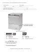
Installation Manual with Service Replacement Parts Undercounter High Temperature Dishwasher Model: 301HT M2 High temperature dishwasher with built-in electric booster Dishwasher Serial No. Issue Date: 1.9.09 Manual P/N 114150 rev. B www.moyerdiebel.com P.O. Box 4183 Winston-Salem, NC 27115 336/661-1992 Fax: 336/661-1660 Toll-free: 800/858-4477 Beginning with S/N 61017 and above 2674 N.
For future reference, record your dishwasher information in the box below. Model Number__________________________ Serial Number_______________________ Voltage________________Hertz_____________ Phase__________________ Moyer Diebel Service Agent __________________________________ Tel:______________________ Moyer Diebel Parts Distributor _________________________________ Tel:______________________ The data plate with model and serial number is mounted the lower right-side of the machine.
ATTENTION: Complete the back of the POSTAGE PAID WARRANTY CARD below, then cut along the dashed lines and mail immediately to make sure that your machine warranty is validated. USE CANADIAN WARRANTY CARD IN CANADA AND USA WARRANTY CARD IN THE UNITED STATES. NO POSTAGE NECESSARY IF MAILED IN THE UNITED STATES BUSINESS REPLY MAIL FIRST-CLASS MAIL PERMIT NO.
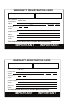
WARRANTY REGISTRATION CARD Serial # Model Date of Installation: Company Name: Address: Telephone #: ( ) --- (Street) State or Province Zip Code Contact: Installation Company: Address: Telephone #: Contact: This Card Must Be Returned to Validate Machine Warranty: IMPORTANT IMPORTANT WARRANTY REGISTRATION CARD Serial # Model Date of Installation: Company Name: Address: Telephone #: ( ) --- (Street) State or Province Zip Code Contact: Installation Company: Address: Telephone #: Contact: This
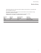
Revision History Revision History The Revision History can contain part number changes, new instructions, or information that was not available at print time. We reserve the right to make changes to this manual without notice and without incurring any liability by making the changes. Equipment owners may request a revised manual, at no charge, by calling 1 (800) 858-4477 in the USA or 1 (800) 263-5798 in Canada. Revision Date Revised Pages Serial Number Effectivity Revision Description 4.15.
Limited Warranty Limited Warranty Moyer Diebel Limited, P.O. Box 4183, Winston-Salem, North Carolina 27115, and P. O. Box 301, 2674 North Service Road, Jordan Station, Ontario, Canada L0R 1S0 warrants machines, and parts, as set out below.
Table of Contents Table of Contents Revision History_ _____________________________________________________________ i Limited Warranty______________________________________________________________ ii Model Descriptions___________________________________________________________ iv Installation _ _________________________________________________________ 1 Receiving__________________________________________________________________ 1 Electrical Connection______________________________________________________
Model Descriptions Model Descriptions Model 301HT M2: High temperature hot water sanitization undercounter dishwasher with a 40°F/22°C rise built-in stainless steel electric booster heater. Rinse-Sentry to ensure 180°F/82°C final rinse water temperature Pressure regulating valve (PRV) Built-in detergent and rinse-aid chemical dispensing pumps 13" door opening clearance 1 flat-bottom dish rack and 1 peg dish rack 1 year parts and labor warranty.
Installation Receiving 1. Check the corrugated box that protected the dishwasher during shipment for punched holes or impact marks. 2. Inspect the shipping pallet for splintered or broken boards. 3. Inspect the exterior of the dishwasher while still mounted on the pallet for signs of damage. 4. If no damage is found, proceed with lifting the dishwasher from its pallet. Be careful to lift the dishwasher by the main frame if using a forklift. 5.
Installation Receiving Care should be taken when lifting the machine to prevent damage. The machine is normally shipped on a skid enclosed by straps. When transporting the machine, use a lift truck or fork lift, positioning the box properly on the forks. 1. Immediately after unpacking your machine, inspect for any shipping damages. If damage is found, save the packing material and contact the carrier immediately. 2. Remove the dishwasher from the skid.
Installation Electrical Connections Note: Leave enough electrical cable behind the machine so that the dishwasher can be pulled forward a minimum of two feet to be serviced. Warning: Electrical and grounding connections must comply with all local electrical codes or in the absence of local codes then connections must comply with the National Electrical Code. Warning: When working on the dishwasher, disconnect the main electric service and tag it to indicate work is being done on that circuit. 1.
Installation Plumbing Connections Water Connections 1. Connect the hot water supply to the fill hose provided with a 3/4" NPT fitting. 2. Install a manual shut-off valve in the water supply line to accommodate servicing the machine. The shut-off valve should be the same size or larger than the supply line and installed as close to the dishwasher as possible. 3. Install a 3/4" pressure reducing valve (PRV) (supplied with machine) in the water supply line, and set at 20-22 PSI/138-151kPa.
Installation Chemical Dispensers ATTENTION: Chemical dispensers must be electrically grounded in compliance with applicable electric codes. adapter (supplied by others). Do not connect drain hose to a 90° drain fitting. Detergent The machine is equipped with an automatic detergent dispensing pump system. 1. Use a qualified detergent/chemical supplier for your detergent. 2. Your machine is supplied with a detergent dispensing pump that is internally wired and ready for use.
Installation Initial Start Up 1. The built-in stainless steel electric booster was shipped without water. 2. A manila card located above the power switch explains how to turn the machine on for the first time. Initial Start-up: 1. Check the placement of the dishwasher: Compare the machine location with the building plan. 2. Check that all options and/or accessories are installed. 3. Remove protective white wrapping, tape, and other packing materials and discard. 4.
Installation Initial Start Up The following is a summary of your model 301HT dishwasher operating cycle: 1. The door must be closed to begin the cycle. 2. Press the POWER button to fill the wash tank. 3. The booster heater comes on when the correct water level has been reached. 4. Press and hold the START button to start the cycle. NOTE : After pushing the start button the first cycle of each day could take at least 15-20 minutes if the machine was not allowed to warm up first. 5.
Operation Operation Operation Procedures 1. Check that the spray arms, overflow tube and scrap screens are in place. 2. Close the door. Press the POWER switch. The tank will begin to fill with water. This procedure is only needed when the tank is empty. 3. When the tank is full, check the wash tank temperature gauge. Minimum wash temperature is 150°F/66°C. 4. Scrap and preflush all items to be washed, load items into rack. Wash only one layer of silverware in a rack at a time.
Cleaning Cleaning After Meal Periods or 8 Hours of Operation 1. Press power switch OFF 2. Remove the overflow tube and press and hold the DRAIN switch to drain the machine. 3. Wipe the interior to remove any debris. 4. Clean the screens after every meal period and more frequently during heavy usage. Do not allow screens to become clogged with debris. 5. Inspect wash and rinse arms. Clean if necessary. 6. Replace overflow tube. 7. Close door. 8. Press the power button to refill machine. Weekly 1.
Cleaning De-liming Danger: Death or serious injury may result when de-liming solution is mixed with sodium hypochlorite (chlorine bleach) sanitizing agent. Mixing may cause hazardous gases to form. De-liming solution and other acids must never be mixed with chlorine, iodine, bromine, or fluorine. Caution: Skin contact with de-liming solutions can cause severe irritation and possible chemical burns. Always wear protective clothing when handling chemicals.
Maintenance Daily Maintenance Maintenance Keep your dishwasher and the surrounding area clean. Daily1. Maintenance 2. Immediately report loose, broken missing to your supervisor. 1. Check the rinse temperature during theorfinal rinse.parts The final rinse must be 180°F/82°C minimum. 3. Check drains for flow restrictions. 2. Clean the scrap screens after 4. Check the dishwasher forevery leaks.meal period. 6. At5.
Troubleshooting Troubleshooting In order to find the cause of a breakdown or abnormal operating condition in your dishwasher please ensure that: 1. All power switches are ON. 2. Drain overflow tube is in place and seated. 3. Wash spray arm nozzles and rinse nozzles are clean. 4. Spray arms are in their proper positions. 5. Pump intake and wash tank screens are clean and properly positioned. 6. Detergent and rinse-aid dispensers are adequately filled. 7. Door is fully closed.
Troubleshooting Troubleshooting Condition Cause Solution Insufficient pumped spray pressure Clogged pump intake screen. . . . . . Clogged spray pipe . . . . . . . . . . . . . Scrap screen full. . . . . . . . . . . . . . . . Low water level in tank. . . . . . . . . . . Defective pump seal. . . . . . . . . . . . . Clean Clean Must be kept clean and in place Check drain and overflow tube Contact service agent Insufficient final rinse or no final rinse Clogged rinse nozzle and/or arm. . .
Blank Page This Page Intentionally Left Blank 14
Service Replacement Parts Service Replacement Parts Illustrations Page Hood and Tank Assembly . . . . . . . . . . . . . . . . . . . . . . . . . . . . . . . . . . . . . . . . . . . . . . . . . . . 16 Door Assembly . . . . . . . . . . . . . . . . . . . . . . . . . . . . . . . . . . . . . . . . . . . . . . . . . . . . . . . . . . . 18 Wash Tank Heater and Chemical Dispensers . . . . . . . . . . . . . . . . . . . . . . . . . . . . . . . . . . . . 20 Fill Piping Assembly . . . . . . . . . . . . . . . . . .
Hood and Tank Assembly 11 1 10 7 11 2 12 12 13 A 7 3 12 7 3 9 11 8 12 4 11 5 7 16 6
Hood and Tank Assembly Item No. Part No.
Door Assembly 1 2 1 3 2 4 3 4 5 18 5 6 17 7 6 7 8 26 8 25 9 24 20 27 19 9 23 22 13 21 12 11 27 10 16 14 15 14 18
Door Assembly Item No. 1 2 3 4 5 6 7 8 9 10 11 12 13 14 15 16 17 18 19 20 21 22 —— 23 24 25 —— 26 27 Part No.
Wash Tank Heater and Chemical Dispensers 1 2 3 8 13 Detergent pump 13 4 9 10 11 4 12 7 Rinse-aid pump 22 4 4 14 15 17 16 18 19 20 21 20 5 6
Wash Tank Heater and Chemical Dispensers Item No. Part No. Description Qty.
Fill Piping Assembly 22
Fill Piping Assembly Item No. Part No. 1 2 3 4 H36156 0502651 0503679 H00182 5 – 6 7 8 9 10 11 12 13 14 15 16 17 18 19 20 21 22 23 24 25 26 27 28 100500 900836 0502651 H36173 H36289 H36607 H36290 H160121 H25239 H34733 H25011 H25778 H18472 H25263 H25010 H26629 H36172 H36349 H280607 H160117 H36032 H33344 H34996 H200415 107550 Description Qty.
Drain Assembly To Drain 17 1 2 3 4 6 8 9 5 7 18 13 17 14 10 11 20 14 19 12 16 14 15 24
Drain Assembly Item No. Part No. Description Qty.
Wash and Rinse Piping Assembly 2 1 3 4 5 6 7 BOTTOM OF TANK 8 5 4 A 9 10 10 11 12 13 A 26
Wash and Rinse Piping Assembly Item No. Part No. Description Qty. Unit 1 0502563 Jubilee Clip 1 ea 2 110215 Screw SS 1 ea — 107873 Gasket 1 ea 3 H35509 Hub, Upper Arm 1 ea 4 0503674 Clamp, Hose 2 ea 5 H00182 Hose, Blue Rinse A/R ft.
Wash and Rinse Arm Assemblies 1 2 3 4 1 5 6 6 8 9 7 8 6 7 6 5 1 4 9 2 3 1 28
Wash and Rinse Arm Assemblies Item No. Part No. Description Qty. Unit *1 ----------- Bearing, Wash Arm 4 ea 2 112549 Hub, Wash Arm 2 ea 3 H420548 Assy, Wash Arm Complete 2 ea 4 112550 Locknut, Wash Arm 2 ea 5 H34998 Nut Spacer 2 ea 6 H190663 Bushing, Rinse Arm 4 ea 7 H36257 Rinse Nozzle 6 ea 8 H36275 Pin, Revolving Rinse Arm 2 ea 9 H36211 Rinse Arm 301 2 ea * Use Kit No. 0712749 whenever a wash arm bearing needs to be replaced.
Wash Pump/Motor Assembly 30
Wash Pump/Motor Assembly Item No. Part No. Description Qty. Unit 1 H36354 Pump Body 1 ea 2 110285 Gasket Pump Body 1 ea 3 H26204 Impeller 1 ea 4 H36355 Shaft Seal 1 ea 5 H36356 Flange Wash Pump 1 ea – H36129 Wash Pump/Motor Assy.
Booster Heater Assembly 6 2 5 7 5 6 8 4 9 10 32 3
Booster Heater Assembly Item No. Part No. Description Qty. Unit 1 H36250 Heater 4000W 230/380V, 40°F/22°C Rise 1 ea --- H33400 Heater 6000W 230/380V 70°F/39°C Rise 1 ea 2 H161123 Element Cap 1 ea 3 109985 O-ring 1 ea 4 H35816 Rinse-aid Inlet Fitting 1 ea 5 0503679 Clamp, Hose 2 ea 6 H00182 Hose, Blue A/R ft.
Control Panel Assembly 11 10 5 3 4 1 2 34 7 6 8 9
Control Panel Assembly Item No. Part No. Description Qty.
Control Cabinet Assembly 36
Control Cabinet Assembly Item No. Part No. Description Qty.
Blank Page This page intentionally left blank 38
Electrical Schematics and Timing Chart Electrical Schematic and Timing Chart 39
Electrical Schematic 40
Timing Chart 41
42