
Product Manual


6
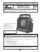
Mr. Heater | Portable Propane Heater Operating Instructions and OwnerÊs Manual
MAINTENANCE:
Always keep the heater area clear and free from
combustible materials, gasoline and other flammable
vapors and liquids.
Keep the vent areas
(slots in the bottom
and the top at the
front of heater)
clear at all times.
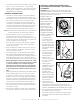
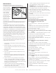
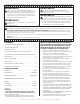
Visually inspect the
pilot flame and
burner periodically
during use. The
pilot flame should
be blue in color
(not yellow) and will extend beyond the thermocouple. The
flame will surround the thermocouple just below the tip,
see Figure 5.
A slight yellow flame may occur where the pilot flame
and main burner flame meet. The burner should be bright
orange (with a slight blue color around the border, a red-
orange haze that is visible on the ceramic tile is acceptable)
and without a noticeable flame. A blue flame that rolls out
at the top of the ceramic tile indicates an accumulation of
dust, lint or spider webs inside the casing assembly and
main burner assembly. If the pilot is yellow or the burner
has a noticeable flame, cleaning may be required. Use the
following procedure to inspect the casing assembly and
main burner assembly.
It is necessary to periodically check the burner orifice and
burner venturi tube to make sure they are clear of insects/
nests or spider webs that may accumulate over time. A
clogged tube can lead to a fire.
1 Allow heater to thoroughly cool before performing any
maintenance.
2 Remove disposable 1 lb. cylinder from heater or turn
OFF gas supply at remote cylinder valve, and disconnect
hose from heater.
3 Remove (4) four screws that secure the rear cover to
the Heater.
4 Pivot cover outward from bottom. Release from 2 top
clips. Set aside.
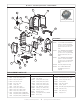
5 Remove (4) four burner retaining screws and fuel line
from burner assembly. Remove burner assembly from
back of housing.
6 Inspect interior of casing assembly for accumulation
of dust, lint or spider webs. If necessary, clean interior
of casing assembly with a vacuum cleaner or apply air
pressure. Do not damage any components within casing
assembly when you are cleaning.
7 Inspect and clean main burner orifice (threaded into
orifice holder). Orifice holder is attached to the burner
assembly venturi with (2) two screws.
8 Inspect and clean pilot (mounted to bracket) by using a
vacuum or apply air pressure through the holes in the
pilot indicated by the arrows in Figure 5.
WARNING: Never use needles, wires, or similar
cylindrical objects to clean the pilot to avoid damaging
the calibrated orifice that controls the gas flow.
9 Apply air pressure (max. 30 psi.) into ceramic tile of
burner assembly and the venturi tube (ref. item #16) to
remove dust, lint or spider webs.
10 Reassemble main burner orifice holder onto the burner
assembly.
11 Reinstall burner assembly into the heater housing
12 Reinstall fuel line and check for leaks.
13 Install heater back cover.
TROUBLESHOOTING INFORMATION:
If Spark electrode does not produce spark.
CHECK
• Spark electrode broken – replace ODS (Oxygen Depletion
Sensor).
• Igniter wire may not be attached to spark electrode,
ground wire may not be attached to frame - attach.
• Igniter wire damaged – replace.
• Piezo igniter defective – replace gas valve assÊy.
If Spark electrode produces spark but pilot does not light.
CHECK
• No gas to heater – install disposable cylinder or connect
hose and turn on valve at remote cylinder.
• „PILOT‰ position not properly aligned – turn gas control
knob to „PILOT‰ position and depress.
• Pilot is blocked from spider web or dirt – clean pilot, see
MAINTENANCE.
If Pilot flame does not stay lit when knob is released.
CHECK
• Control knob in „PILOT‰ position not completely
depressed or held in long enough to purge air from lines.
• Pilot flame not surrounding thermocouple – clean pilot,
see MAINTENANCE.
• Pilot Assembly defective – replace.
• Tip switch wires disconnected – connect.
If Main burner does not ignite.
CHECK
• Main burner orifice is blocked – clean burner, see
MAINTENANCE.
If Heater keeps shutting “OFF” during normal operation.
CHECK
• Pilot is blocked – clean pilot, see MAINTENANCE.
• Provide minimum fresh air opening of 9 square inches
(example 3‰ x 3‰ opening).
• Tip over switch activated from bumping heater. Re-light
• Regulator defective - Replace regulator.
• Internal contamination - Replace control valve and
regulator.
• Call Technical Services for additional information.
Figure 5