
Manual


E5
Installation instructions and Owner’s Manual
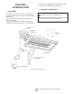
CHAPTER II
HEATER INSTALLATION
1. GENERAL INSTALLATION INFORMATION
AND REQUIREMENTS
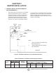
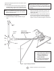
• The required minimum clearances to combustible
surfaces are illustrated in Figure 2 and Table 3.
As shown on Figure 2, the front of the heater is
installed at the minimum required clearance to
combustible surfaces and toward open space,
and then the other sides must have a minimum
clearance of 16 inches to combustible surfaces.
EXHAUST
VENT
CEILING
14”
MINIMUM
16”
MINIMUM
48”
MINIMUM
OPEN
WORKSHOP DOOR
HEATER
WALL BRACK-
ET
16”
MINIMUM
14-1/2”
FLOOR LINE
30
1. ONLY FLUE SIDE OF HEATER CAN
BE ELEVATED (30
o
).
2. HEATER SIDE REFLECTOR MUST
BE HORIZONTAL.
NOTE:
Figure 2. Installation Clearances to Combustible Surfaces
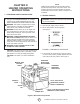
Table 3. Installation, Ventilation and Mounting Information
BTU/HR. RATING NORMAL
MODEL GAS MOUNTING CLEARANCES TO COMBUSTIBLE SURFACES
NO. NAT. L.P. POSITION TOP SIDES BACK BELOW
MH25NG 25,000 — 30
o
14” 16” 16” 48”
MH25LP — 22,000 30
o
14” 16” 16” 48”
The clearances to combustibles represent a surface
temperature of 90°F (32°C) above room temperature.
Building materials with low heat tolerance may be
subject to degradation at lower temperatures. It is the
installer’s responsibility.