
Manual


E8
Installation instructions and Owner’s Manual
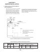
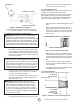
LEAVE 2 THREADS BARE
USE MODERATE AMOUNT OF PIPE DOPE
3/4” MAXIMUM
THREAD LENGTH
1/2” BLACK PIPE
GAS VALVE BODY
1/2” MAXIMUM
DEPTH OF IN-
SERTS INTO GAS
VALVE
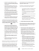
Refer to National Electrical Code NFPA70-1993 and
for Canadian installations to current CODE C22.1-
3. CONNECTING HEATER TO GAS SUPPLY
WARNING: Depending on local codes and require-
ments and the installer’s skill level, the sizing and
installation of gas lines required to safely and efciently
supply the heater may require the assistance of a pro-
fessional. If in doubt as to these requirements, discuss
the requirements of this manual with the dealer from
whom the heater was purchased and your gas supplier.
3.1 Gas Supply Requirements
• See Tables 1 and 2 for gas supply minimum, maxi-
mum, operating, and manifold pressures for both
heater models. Pressures are provided in inches of
W.C. (water column). Also, see heater rating plates
located on the heater.
WARNING: Model MH25NG is designed to burn
natural gas and it comes equipped with a regulator.
The regulator is built into the gas valve. The maximum
inlet pressure to this regulator is 1/2 psi (14 in. W.C.) If
gas line pressure exceeds 1/2 psi, then an additional
regulator must be installed before the heater/regulator
to step down the pressure to a maximum of 1/2 psi.
• Most non-commercial natural gas services provide
a line pressure of 4 oz. (6.9 in. W.C.). If in doubt
consult your natural gas supplier.
• To ensure the best performance from your natural
gas heater make sure the supply manifold pres-
sure is at least 6” W.C.
WARNING: Model MH25LP is designed to burn
liqueed petroleum (LP) gas and it comes equipped
with a regulator. The regulator is built into the gas
valve. The maximum inlet pressure to this regulator
is 1/2 psi (14 in. W.C.). If gas line pressure exceeds
1/2 psi, then an additional regulator must be installed
before the heater/regulator to step down the pressure
to a maximum of 1/2 psi.
• To ensure the best performance from your LP gas
heater, make sure the supply manifold pres-
sure is at least 1/2 psi (14 in W.P.).
3.2 Piping Requirements
All piping installed must comply with local codes and
ordinances or with National Fuel Gas Code,
ANSI Z223.1 (NFPA 54), whichever takes precedence.
When installing piping, the following requirements
must be taken into consideration: Canadian installa-
tions must comply with the B149.1.2 Gas Code.
• Use new properly reamed black pipe free from
chips.
• Apply a good quality pipe compound to all
male threads as shown in Figure 5 prior to as-
sembly. If LP gas is the fuel, ensure that pipe
compound is resistant to LP gas. Do not use
Teon™ tape.
Figure 5. Pipe Compound Application
• Male threads on pipe to be installed into gas
valve shall meet the requirements of Figure 6.
Threads longer than those shown in the gure
may cause gas valve distortion and malfunc-
tion.
• A sediment trap meeting the typical require-
ments of Figure 7 shall be installed in the line
to the gas valve.
• A dedicated shutoff valve for the heater must
be installed in the gas supply line.
3.3 Piping Installation
While ensuring that all of the above gas supply re-
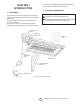
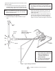
THERMOSTAT
POWERPILE GAS VALVE
POWERPILE GENERATOR
Figure 4. Connection Diagram
Figure 6. Gas Valve Connection Requirements