
Manual


E9
Installation instructions and Owner’s Manual
quirements and piping requirements are fullled, install
piping as follows:
A. In accordance with the above piping requirements,
assemble piping, sediment trap, shutoff valve, and
necessary ttings. Tighten all components securely.
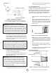
WARNING: Failure to ensure that male threads on
pipe to be installed into gas valve meet the require-
ments of Figure 6 may cause gas valve damage,
distortion and malfunction.
B. Install a threaded nipple, prepared in accordance
with paragraph 3.2 into gas valve.
C. Connect gas piping to nipple installed in the gas
valve.
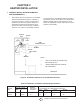
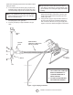
SUPPLY
LINE
SHUTOFF
VALVE
1/2”
TEE
3”
CAP
NIPPLE
HEATER
RIGID PIPE WITH
UNION OR A FLEXIBLE CON-
NECTOR TO HEATER
Figure 7. Typical Piping Installation
NOTE:
1. ONLY USE A PIPE COMPOUND
WHICH IS RESISTANT TO
LIQUIFIED GASES ON LP
INSTALLATIONS.
2. FITTINGS SHOWN ARE NOT
INCLUDED WITH HEATER.
WARNING: When testing gas piping use only a
soap and water solution. Do not use a match or
other ame for leak testing. If during leakage check
gas is smelled, turn off the gas supply and ventilate
building.
D. Ensure the building is properly ventilated. Without
lighting the pilot light of the heater, open the gas
supply valve and pressurize the piping up to the
heater’s gas valve.
E. Using a brush, apply a soap and water solution to
all connections and look for bubbles indicating a
leak. If a leak is detected, turn off gas supply and
tighten connections. Retest and tighten connections