
Product Manual


Compact Unit / Utility Heater
10
Operating Instructions and Owner’s Manual
WARNING
Electric shock hazard. Can cause injury or death.
Do not use this heater if any part has been
under water. Immediately call a qualified service
technician to inspect the furnace and to replace
any part of the control system and any gas
control which has been under water.
WARNING
Electric shock hazard. Can cause injury or death.
Before attempting to perform any service or
maintenance, turn the electrical power to unit
OFF at disconnect switch(es). Unit may have mul-
tiple power supplies.
WARNING
Danger of explosion. Can cause injury or product
or property damage. If over-heating occurs or if
gas supply fails to shut off, shut off the manual
gas valve to the appliance before shutting off
electrical supply.
WARNING
Danger of explosion and fire. Can cause injury or
product or property damage. You must follow
these instructions exactly.
GAS CONNECTIONS
When connecting gas supply lines, the length of the piping run from
the meter to the heater must be considered in determining the pipe
size to avoid excessive pressure drop. A line pressure of 7” WC
(178mm WC) for natural gas should be maintained when sizing the
piping.
A line pressure of 13” WC (330mm WC) should be maintained for
propane (LP) gas. NOTE: Compounds used on threaded joints or gas
piping must be resistant to the actions of Liquefied petroleum gasses.
WARNING: TO PREVENT HEATER DAMAGE. WHEN USING A
PROPANE TANK TO SUPPLY HEATER, A MINIMUM 11”W.C.
LOW PRESSURE REGULATOR TO A MAXIMUM 14”W.C. LOW
PRESSURE REGULATOR IS REQUIRED. THIS REGULATOR
MUST BE INSTALLED BETWEEN THE TANK AND THE HEATER.
Regulator not supplied with heater.
For correct sizing of piping, refer to the (American) National Fuel Gas
Code ANSI Z223.1, or (Canada) CSA B149.1, National Gas and Pro-
pane Installation Code or consult the utility having jurisdiction.
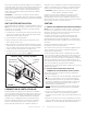
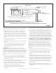
A drip leg should be installed in the vertical pipe run to the unit. In
some localities, codes may require that a manual main shutoff valve
and union (furnished by installer) be installed external to the unit.
Union must be of the ground joint type. A drip leg should be readily
accessible to permit cleaning and empting. See figure 7.
NOTE: Leave a min of 4’’ clearance to the electrical connections box
on the back of the heater to allow for access.
A 1/8” NPT plugged tap shall be installed immediately upstream of the
gas supply connection to the heater. The purpose of this is to be able
to check for proper gas pressure entering the heater.
LEAK CHECK
CAUTION DO NOT use matches, candles, flame or other sources of
ignition to check for gas leaks.
After gas piping is completed, carefully check all piping connections,
(field and factory), for gas leaks. Use a soap solution or other pre-
ferred means.
Due to the natural heating cycles and vibration of this unit it is recom-
mended, as part of its annual maintenance, to check these connec-
tions for proper tightness and leak-check with a soap solution or other
preferred means prior to putting into service.
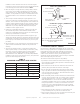
IMPORTANT The heater and its individual shut off valve must be
disconnected from the gas supply piping system during any pressure
testing of that system at test pressures in excess of 1/2 psig (3.45kPa).
The appliance must be isolated from the gas supply piping system by
closing its individual manual gas shutoff valve during any pressure
testing of the gas supply system at test pressures equal to or less than
1/2 psig (3.45kPa). See figure 8.
NOTE In case emergency shutdown is required, shut down main gas
valve and disconnect main power to unit. These devices should be
properly labeled by the installer.
START-UP OPERATION
UNIT START–UP
FOR YOUR SAFETY READ BEFORE LIGHTING
BEFORE LIGHTING smell all around the appliance area for gas. Be
sure to smell next to the floor because some gas is heavier than air
and will settle on the floor.
Use only your hand to move the gas control knob to the on position.
Never use tools. Do not use excessive force to switch valve from off to
on position. Force or attempted repair may result in a fire or explosion.
MHU 50/80/125 unit heaters are equipped with an automatic spark
ignition system. There is no pilot. In case of a safety shutdown, move
thermostat switch to OFF, then return the thermostat switch to HEAT
position.
Should overheating occur, or the gas supply fail to shut off, shut off
the manual gas valve to the appliance before shutting off the electrical
supply.
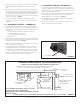
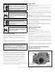
GAS VALVE OPERATION FOR HONEYWELL
VR8205M SERIES VALVE
MANIFOLD PRESSURE ADJUSTMENT
SCREW
(UNDER CAP)
GAS VALVE ROTARY SWITCH KNOB
MANIFOLD
PRESSURE
TAP
GAS
SUPPLY
INLET PRESSURE TAP
FIGURE 9