
Product Manual


Compact Unit / Utility Heater
5
Operating Instructions and Owner’s Manual
These units are certified for residential applications. For installation in
a residential garage, these units must be installed so that burners and
ignition source are located no less than 18” (457mm) above floor.
Heater must be located or protected to avoid physical damage by
vehicles. Refer to CSA B149.1, Natural Gas and Propane Installation
Code current edition.
IN CANADA: In a confined area, the heater must be installed in
accordance with the CSA B149.1, Natural Gas and Propane Installation
Code. Be sure to check with local codes and ordinances for additional
requirements.
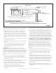
UNIT HEATER INSTALLATION
Unit is shipped ready for installation. Unit may be installed as shown in
figure 1 or inverted 180
o
depending on desired location as governed
by clearances, vent connection, air direction, gas supply, electrical
supply and service accessibility.
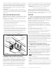
1. If installing unit in an inverted position: Remove and retain screws
securing door and rotate door 180o. Secure with retained screws.
Rotate louvers directing airflow as desired.
2. Choose location for mounting brackets.
3. Remove and retain three screws along top edge (bottom edge
when inverted) of front of unit.
4. Align screw holes on mounting bracket with holes along top edge
(either upright or inverted) of unit. Secure one mounting bracket to
front of unit with retained screws. Secure other mounting bracket
to back of unit with screws retained on the back of unit.
5. To support unit, secure mounting bracket to ceiling joist or truss.
Unit may also hang on rods as shown in figure 1.
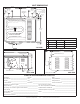
INSTALL UNIT / UTILITY HEATER
FIGURE 1
MOUNTING
BRACKETS (2)
SUPPORT
RODS
COMBUSTION & VENTILATION AIR
Adequate facilities for supplying air for combustion and ventilation
must be provided in accordance with the latest edition of section 5.3,
Air for Combustion and Ventilation, of the National Fuel Gas Code,
ANSI Z223.1, in the U.S.A., CSA B149.1 Natural Gas and Propane
Installation Code, or applicable provisions of local building codes.
All gas fired appliances require air to be used for the combustion
process. In many buildings today, there is a negative indoor air
pressure caused by exhaust fans, etc. If sufficient quantities of
combustion air are not available, the heater or another appliance will
operate in an inefficient manner, resulting in incomplete combustion
which can result in the production of excessive carbon monoxide.
CAUTION:Insufficient combustion air can cause headaches,
nausea, dizziness, asphyxiation or death.
If indoor air is to be used for combustion, it must be free of the
following substances or the life of the heat exchanger will be
adversely affected: chlorine, carbon tetrachloride, cleaning solvent,
halogen refrigerants, acids, cements and glues, printing inks, fluorides,
paint removers, varnishes, or any other corrosives.
VENTING
A – GENERAL RECOMMENDATIONS AND REQUIREMENTS
NOTE: The vent is a passageway, vertical or nearly so, used to convey
flue gases from an appliance, or its vent connector, to the outside
atmosphere. The vent connector is the pipe or duct that connects a
fuel-gas burning appliance to a vent or chimney.
Unit heaters must be vented in compliance with all local codes
or requirements of the local utility, the current standards of the
(American) National Fuel Gas Code, ANSI Z223.1 or (Canada) CSA
B149.1 Natural Gas and Propane Installation Code, and the following
instructions.
Do not intermix different vent system parts from different
manufacturers in the same venting system.
Vent connectors serving Category I and Category II Appliances shall
not be connected into any portion of mechanical draft systems
operating under positive pressure.
A metal stamped/extruded transition is supplied with this certified
unit. It must not be modified or altered and must be installed on the
outlet of the induced draft blower assembly prior to the installation
of the vent or vent connector. Failure to comply with this requirement
will void the certification of the unit by the approval agencies. All
joints shall be secured with at least two corrosion resistant screws. All
joints must be checked for gas tightness after installation.
The heater and the venting system shall be inspected once a year by a
qualified service agency.
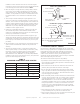
B – VERTICAL VENTS USING METAL VENT PIPE
– COMMERCIAL AND RESIDENTIAL INSTALLATIONS
MHU compact unit heaters are listed as Category I appliances for
vertical vent installations.
1. US: MHU unit heaters are to be used with NFPA- or ANSI-approved
chimneys, U.L. listed type B-1 gas vents, single wall metal pipe,
or listed chimney lining system for gas venting where applicable,
as well as the modifications and limitations listed in figure 2. Seal
single wall vent material according to the section A - General
Recommendations and Requirements.
Canada: Listed Category I Unit Heaters are to be used with Type
B gas vent. Minimum clearances of gas vent from combustible
material: 1 inch (25 mm)
2. The vent connector shall be 4”(102 mm) diameter on 50 & 80
& 125k units. In all cases, a flue transition piece (supplied) is
required to fit over the outlet of the induced draft assembly on the
appliance.
3. Keep the vent connector runs as short as possible with a minimum
number of elbows. Refer to the (American) National Fuel Gas Code
ANSI Z223.1 or (Canada) CSA B149.1 Natural Gas and Propane