
Generators Installation Sheet


INSTALLATION INSTRUCTIONS
FOR MODELS: MS-SUPER 4E, MS-SUPER 5E AND MS-SUPER 6E
1.
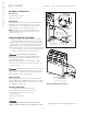
Install each unit as in a single installation. Install the two generators as close to each other as possible.
2.
Shock Hazard.
Power must be disconnected at the main electrical supply before removing
steam generator covers.
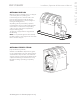
3. Connect the iSteam
®
, AirTempo
®
or iTempo/Plus
®
control to either generator per the control instructions..
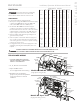
4. Remove one knock-out on each generator as shown. Insert the ends of interconnecting cable provided (PN 103904)
through the knock-outs as shown in the Diagram on page 5. Connect each end to the printed circuit board as shown.
5. Connect separate plumbing and power supplies for each unit.
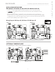
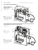
Wiring Diagram: MS-Super 4E, MS-Super 5E, MS-Super 6E
AutoFlush
(optional)
iTempo/Start
(optional)
iSteam, AirTempo
or iTempo/Plus
AutoFlush
(optional)
Do Not
Connect
Control
FAC TORY
WIR ING
FIE LD
WIR ING
L E G E N D
(All Diagrams)
{
CONTACTOR
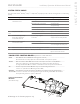
PRIMARY UNIT SECONDARY UNIT
AutoFlush
(optional)
Steam Genie
(optional)
iSteam, AirTempo
or iTempo/Plus
AutoFlush
(optional)
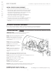
PLUG THIS END
TO MASTER UNIT
PRIMARY UNIT
SECOND UNIT
TO THIRD UNIT
TO FOURTH UNIT
TO FIFTH UNIT
Optional Tandem Cable for 2-5 Generators
Length is 30 ft. PN: 103917
OPTIONAL TANDEM CABLE
For connecting more than 2 steam generators in tandem
11
I N S T A L L E R
mr
.
steam
®
Installation, Operation & Maintenance Manual
__________________________________________________________________________
WARNING
!