
Control Unit Installation Sheet


mr
.
steam
®
INSTALLER INFORMATION
__________________________________________________________________
5
3a
3b
4a
4a
5b
5a
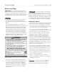
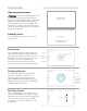
Locating the Control
Determine the desired installation location of the control. The iSteam
®
3
controls are designed to be installed inside or outside the steam room
as a matter of personal preference. If the control is installed inside
the steam room:
• Locate the control 4-5 feet above the oor near the bather seating area.
• The control features an integral temperature sensor. Locate the control in a
location representative of the desired steam bathing temperatures. Do not
locate the control above or near the steam head or direct steam emissions.
• Locate the control on a vertical wall.
• The control cable is 30 feet. Insure that the control and steam generator are
located accordingly.
IMPORTANT NOTES:
• If required, contact MrSteam to purchase an optional 60’ iSteam3
control cable part number 104117-60.
• If the control is installed outside the steam room a Remote Temperature
Probe Part Number MSTS must be installed inside the steam room.
Refer to the MSTS installation manual before installing the control.
• Insure MrSteam steam generator is iSteam3 compatible and has
a serial number 1174000 or higher.
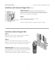
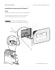
Installation with Optional Rough-In Box
A rough-in box is supplied with iSteam3 for new construction. The rough
-in box will allow precise location of the iSteam3 control and provide a
secure and easily identifiable place for the cable while the steam room is
being constructed.
STEP 1
Take the rough-in box out of the package. Remove the two
screws (1a ) and place them in the top and bottom wings of the rough-in
box (1b).
STEP 2
Select a KNOCK-OUT (2a) to route the control cable into the box.
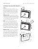
STEP 3 Line up the two TABS (3a) on the right side of the box against a
stud. These TABS help locate the box to sit PROUD of the stud (3b).
STEP 4
SCREW (4a) the two supplied screws into the stud.
STEP 5
Route the CONTROL CABLE (5a) through the back of the rough-in
box and clip it under one of the TABS (5b) that previously held the screws.
The two ends of the control cable are the same.
IMPORTANT NOTE: The control cable should be run in a dedicated 1”
conduit to facilitate installation and service.
1a
1b
1b
2a