Please read this manual carefully before installation and keep it for future reference. Installation Manual Signature Series MCVP* & MCHP* Series Coils Due to updates and constantly improving performance, the information and instructions within this manual are subject to change without notice. Please visit www.mrcool.com/documentation to ensure you have the latest version of this manual.
Signature Series Indoor Coils INSTALLATION INSTRUCTIONS This manual must be left with the homeowner for future reference. This is a safety alert symbol and should never be ignored. When you see this symbol on labels or in manuals, be alert to the potential for personal injury or death. Table of Contents ........................................2 General ........................................................................3 Shipping and Packing List ...........................................
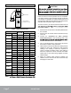
M C V P 24 A N P A MRCOOL 2nd Gen Coil Metering Device O = Orifice T = TXV C = Capillary P = Piston Air Flow M = Upflow/Horizontal V = Upflow H = Horizontal Refrigerant N = R410 R = R-22 Case C = Unpainted U = Uncased P = Painted Coil Dimension A = 14.5 B = 17.5 C = 21 D = 24.5 Capacity (MBTU/H) mrcool.
NOTE: Special procedures are required for cleaning the aluminum coil in this unit. See Page 8 in this instruction for information. Releasing Air Charge General CAUTION The MCV* & MCH* coils are only available cased and include a factory-installed HFC-410A fixed orifice (RFC) metering device that must be replaced if the system match valve. of 500°F. The drain pan must be at least 2" away from a The coil is shipped from the factory pressurized with dry air.
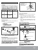
Refrigerant Line Connections 1 PLACE A WET RAG AGAINST COIL CABINET AND AROUND THE SUCTION LINE CONNECTION. 2 BRAZE CONNECTION. ALLOW PIPE TO COOL BEFORE REMOVING WET RAG. Line Sizes The refrigerant line sets should be sized according to the recommendations given in the condensing unit installation instructions. Use Table 1 to determine correct braze to match line set connections. Model Number Suction 18/24 24 30 30/36 36 3/4 Inch 48 49 50/60 60 7/8 Inch WATERSATURATED RAGS Liquid Figure 2.
NOTE: If the system match requires an HFC-410A check/ Leak Testing, Evacuating and Charging expansion valve is installed. Refer to the outdoor unit instruction for leak testing, evacuating and charging procedures. Always leak check entire system before charging. 1. Remove the coil access and plumbing panels. 2. Remove any shipping clamps that secure the liquid line and distributor assembly. 3. Using two wrenches, disconnect the liquid line stub damage the distributor tubes during this process. 4.
Sealing Ducts not connected to a drain line, it must be plugged with the provided cap. WARNING There must be an airtight seal between the bottom of IMPORTANT sealing strips, caulking, or equivalent sealing method between the plenum and the air handler cabinet to ensure a tight seal.
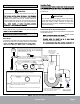
Blower Speed Selection CAUTION and the duct. Drill holes away from refrigerant piping. avoid unit damage. TEST HOLES AIR FLOW Proper air volume must be provided over the evaporator coil. Select a blower motor speed tap that will provide 400 ± 50 CFM per 12,000 Btu/h of cooling capacity (wet coil). A static pressure reading must be taken to see if the pressure drop falls within the proper range. See Table 2.
Cleaning The Coil Maintenance 1. Remove the coil from the cabinet or plenum, and take the coil to an appropriate place to clean it. NOTE Failure to follow instructions will cause damage to the unit. 2. Vacuum or brush the coil to remove matted and 3. If oil deposits are present, spray the coil with a mild household liquid detergent to soften deposits. Do not leave the detergent on the coil for more than 10 minutes. Flush the coil thoroughly with potable water.
Please read this manual carefully before installation and keep it for future reference. Signature Series Consult with the sales agency or manufacturer for details.