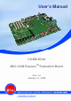
User’s Manual CX-MB-EVA2 MSC COM ExpressTM Evaluation Board Rev. 1.
Preface Copyright Notice Copyright © 2008 MSC Vertriebs GmbH. All rights reserved. Copying of this document, and giving it to others and the use or communication of the contents thereof, are forbidden without express authority. Offenders are liable to the payment of damages. All rights are reserved in the event of the grant of a patent or the registration of a utility model or design. Important Information This documentation is intended for qualified audience only.
CX-MB-EVA2 User's Manual Content 1 ........................................................................................................................... 1 Preface ................................................................................................................ 2 1 1.1 1.2 1.3 2 2.1 2.2 2.3 2.4 3 3.1 3.2 4 General Information...................................................................................... 7 Revisions and Modifications ...........................................
CX-MB-EVA2 User's Manual 4.18 SuperIO ............................................................................................................37 4.18.1 COM Ports ........................................................................................................37 4.18.2 IrDA...................................................................................................................38 4.18.3 PS/2 .................................................................................................
CX-MB-EVA2 User's Manual Illustrations Illustration 1 Block Diagram Base Board........................................................................11 Illustration 2 Positioning of the Connectors...................................................................
CX-MB-EVA2 User's Manual Tables Table 1 COMExpress Connector Rows A and B ............................................................16 Table 2 COMExpress Connector Rows C and D ............................................................18 Table 3 Assignment PCI slot to connector reference ....................................................19 Table 4 Pin out PCI ...........................................................................................................
CX-MB-EVA2 User's Manual General Information 1 General Information 1.1 Revisions and Modifications Revision Date Comment 1.0 January 14, 2009 First release 1.2 Reference Documents [1] COM Express Module Base Specification COM Express Revision 1.0 Last update: July 10th, 2005 [2] ATX Specification atx2_21.pdf Version 2.2 http://www.formfactors.org [3] PCI Local Bus Specification Rev. 2.1 PCI21.PDF Last update: June 1st, 1995 http://www.pcisig.com [4] JILI Specification Jilim120.
CX-MB-EVA2 User's Manual 1.
CX-MB-EVA2 User's Manual 2 Introduction 2.1 Product Description Introduction COM Express modules are compact, highly integrated Single Board Computers. Typically a COM Express module consists of CPU, chipset, memory, video controller, Ethernet controller, BIOS flash and EIDE-, SATA- and USB controller. Interface controllers (e.g. for PCMCIA) or connectors (e.g. RJ45) are implemented on the base board on to which the COM Express module can be mounted via one or two 220-pin SMD-connectors.
CX-MB-EVA2 User's Manual Introduction 40 pin IDE interface Ultra ATA-100/66/33 44 pin IDE interface Ultra ATA-100/66/33 Compact flash interface Spec. v3.0 SATA channels up to 150MB/s 8 USB2.0 root hub interfaces LAN interface max.
CX-MB-EVA2 User's Manual 2.
CX-MB-EVA2 User's Manual 2.
CX-MB-EVA2 User's Manual Mechanics 3 Mechanics 3.1 Dimensions Dimension: 254.5 mm x 36.8 mm Width: 1.6 mm + /-10% Tolerances of the drill holes: +/- 0.1mm in X and Y Tolerances of the diameter: + 0.1 mm 3.2 Assembly notes CXC: 4x M2.5 x 5mm bolt CXB: 5x M2.5 x 5mm bolt CXE: 7x M2.
CX-MB-EVA2 User's Manual Hardware 4 Hardware 4.1 Plug-in Position of the COM Express module Sockets for a COM Express type 2 module is available on the base board. Following form factors are supported: Compact module (Industry Consortium form-factor) Basic module Extended module Specification: Reference: Connector: AMP / Tyco 3-1827233-6 0.
CX-MB-EVA2 User's Manual A30 A31 A31 A32 A33 A34 A35 A36 A37 A38 A39 A40 A41 A42 A43 A44 A45 A46 A47 A48 A49 A50 A51 A52 A53 A54 A55 A56 A57 A58 A59 A60 A61 A62 A63 A64 A65 A66 A67 A68 A69 A70 A71 A72 A73 A74 A75 A76 A77 A78 A79 A80 A81 A82 Hardware AC_RST# GND GND AC_BITCLK AC_SDOUT BIOS_DISABLE# THRMTRIP# USB6USB6+ USB_6_7_OC# USB4USB4+ GND USB2USB2+ USB_2_3_OC# USB0USB0+ VCC_RTC EXCD0_PERST# EXCD0_CPPE# LPC_SERIRQ GND PCIE_TX5+ PCIE_TX5GPI0 PCIE_TX4+ PCIE_TX4GND PCIE_TX3+ PCIE_TX3GND PCIE_TX2+ PCIE_TX
CX-MB-EVA2 User's Manual Hardware A83 LVDS_I2C_CK B83 A84 LVDS_I2C_DAT B84 A85 GPI3 B85 A86 KBD_RST# B86 A87 KBD_A20GATE B87 A88 PCIE0_CK_REF+ B88 A89 PCIE0_CK_REFB89 A90 GND B90 A91 RSVD B91 A92 RSVD B92 A93 GPO0 B93 A94 RSVD B94 A95 RSVD B95 A96 GND B96 A97 VCC_12V B97 A98 VCC_12V B98 A99 VCC_12V B99 A100 GND B100 A101 VCC_12V B101 A102 VCC_12V B102 A103 VCC_12V B103 A104 VCC_12V B104 A105 VCC_12V B105 A106 VCC_12V B106 A107 VCC_12V B107 A108 VCC_12V B108 A109 VCC_12V B109 A110 GND B110 Table 1 COMExpre
CX-MB-EVA2 User's Manual C23 C24 C25 C26 C27 C28 C29 C30 C31 C31 C32 C33 C34 C35 C36 C37 C38 C39 C40 C41 C42 C43 C44 C45 C46 C47 C48 C49 C50 C51 C52 C53 C54 C55 C56 C57 C58 C59 C60 C61 C62 C63 C64 C65 C66 C67 C68 C69 C70 C71 C72 C73 C74 C75 Hardware PCI_RESET# PCI_AD0 PCI_AD2 PCI_AD4 PCI_AD6 PCI_AD8 PCI_AD10 PCI_AD12 GND GND PCI_AD14 PCI_C/BE1# PCI_PERR# PCI_LOCK# PCI_DEVSEL# PCI_IRDY# PCI_C/BE2# PCI_AD17 PCI_AD19 GND PCI_AD21 PCI_AD23 PCI_C/BE3# PCI_AD25 PCI_AD27 PCI_AD29 PCI_AD31 PCI_IRQA# PCI_IRQB# GN
CX-MB-EVA2 User's Manual Hardware C76 GND D76 C77 RSVD D77 C78 PEG_RX8+ D78 C79 PEG_RX8D79 C80 GND D80 C81 PEG_RX9+ D81 C82 PEG_RX9D82 C83 RSVD D83 C84 GND D84 C85 PEG_RX10+ D85 C86 PEG_RX10D86 C87 GND D87 C88 PEG_RX11+ D88 C89 PEG_RX11D89 C90 GND D90 C91 PEG_RX12+ D91 C92 PEG_RX12D92 C93 GND D93 C94 PEG_RX13+ D94 C95 PEG_RX13D95 C96 GND D96 C97 RSVD D97 C98 PEG_RX14+ D98 C99 PEG_RX14D99 C100 GND D100 C101 PEG_RX15+ D101 C102 PEG_RX15D102 C103 GND D103 C104 VCC_12V D104 C105 VCC_12V D105 C106 VCC_12V D106
CX-MB-EVA2 User's Manual 4.2 Hardware PCI Slots Four 32-bit PCI slots are provided according to PCI specification v2.1. The signal assignment for slot 0, slot 1, slot 2 and slot 3 is defined in the COM Express specification. INTA#, INTB#, INTC# and INTD# REQ[0..3]# GNT[0..
CX-MB-EVA2 User's Manual Hardware A22 AD28 A23 AD26 A24 GND A25 AD24 A26 IDSEL A27 3V3 A28 AD22 A29 AD20 A30 GND A31 AD18 A32 AD16 A33 3V3 A34 FRAME# A35 GND A36 TRDY# A37 GND A38 STOP# A39 3V3 A40 SMBCLK A41 SMBDAT A42 GND A43 PAR A44 AD15 A45 3V3 A46 AD13 A47 AD11 A48 GND A49 AD09 Key A52 C/BE0# A53 3V3 A54 AD06 A55 AD04 A56 GND A57 AD02 A58 AD00 A59 5V A60 REQ64# A61 5V A62 5V Table 4 Pin out PCI 20 B22 B23 B24 B25 B26 B27 B28 B29 B30 B31 B32 B33 B34 B35 B36 B37 B38 B39 B40 B41 B42 B43 B44 B45 B46 B4
CX-MB-EVA2 User's Manual 4.3 Hardware PCI Express x1 Slots One PCIe x1 slot is assigned to each of the 6 PCIe lanes of the COM Express module. Note: The order of the connectors has changed on the new layout. Now X6 is near PEG slot. Note : The number of PCIe lanes available will depend on the COM Express module used – not all modules can support 6 PCIe lanes.
CX-MB-EVA2 User's Manual 4.4 Hardware PCI Express x16 Graphics Slot A PCIe x16 graphics slot is provided for insertion of PEG graphics cards. Depending on the chipset the PCIe signals are multiplexed with SDVO signals, thus SDVO modules can be run in this slot as well. SDVO or PCIe graphics will be activated automatically via PullUps of the SDVO I²C interface on the SDVO module.
CX-MB-EVA2 User's Manual Hardware A36 PER_n4 1 B36 A37 GND B37 A38 GND B38 A39 PER_p5 1 B39 A40 PER_n5 1 B40 A41 GND B41 A42 GND B42 A43 PER_p6 1 B43 A44 PER_n6 1 B44 A45 GND B45 A46 GND B46 A47 PER_p7 1 B47 A48 PER_n7 1 B48 A49 GND B49 A50 RSVD B50 A51 GND B51 A52 PER_p8 1 B52 A53 PER_n8 1 B53 A54 GND B54 A55 GND B55 A56 PER_p9 1 B56 A57 PER_n9 1 B57 A58 GND B58 A59 GND B59 1 A60 PER_p10 B60 A61 PER_n10 1 B61 A62 GND B62 A63 GND B63 A64 PER_p11 1 B64 1 A65 PER_n11 B65 A66 GND B66 A67 GND B67 1 A68 PER_p1
CX-MB-EVA2 User's Manual 4.5 Hardware VGA Interface An analog display can be connected via a VGA (VESA DDC) interface.
CX-MB-EVA2 User's Manual 4.6 Hardware LVDS-Interface LCDs can be connected via a single channel LVDS interface: Specification: References: X14 Connector: Hirose DF19G-20P-1H Pinout: Refer to Table 4 Pin 20 can be configured via 0 Ohm resistors to “OPEN” or “GND” Pin Signal name Function 1 VDD Power Supply: +3.3V 2 VDD Power Supply: +3.
CX-MB-EVA2 User's Manual 4.6.2 Hardware Backlight Inverter Interface The supply voltage of the backlight can be adjusted with jumper JP0601. The according position is printed on the PCB. Jumper J5 should be set according to the backlight inverter used. If the inverter needs a low active start signal, jumper J5 has to be set to L (pin1 connected to pin2). If the inverter needs a high active start signal, jumper J5 has to be set to H (pin2 connected to pin3).
CX-MB-EVA2 User's Manual Hardware 4.7 JILI Interface 4.7.1 Standard JILI Connector A standard JILI connector can be used alternatively for connection of LCDs. Both, single and dual channel LCDs, can be connected to the base board via small adaptor boards. Specification: References: X16 Connector: Hirose FH12-40S-0.5SV Pinout: 4.7.2 "standard JILI" according to JILI specification [4] JILI40 Connector Any LCD display can be connected via an adaptor board to the JILI40 connector.
CX-MB-EVA2 User's Manual 4.8 Hardware TV Out A TV-OUT connector is implemented for displaying the video signal on a TV set (or the like). The base board supports the following video signals Composite Video Component Video (YPbPr) S-Video The type of the video signal is defined by the graphics controller on the COM Express module.
CX-MB-EVA2 User's Manual 4.9 Hardware Audio An AC’97 codec V2.2 is connected to the AC link of the COM Express module. Footprint and circuit are compatible to following AC’97 codecs: VIA VT1612A Realtek ALC650 Following LF signals are provided by the AC’97 codec: Mono Microphone Stereo LineIn Stereo LineOut Stereo Headphone Alternatively a VIA VT1708 HDA codec can be connected to the AC link of the COM Express module. The audio interface can be selected with Jumper J0701.
CX-MB-EVA2 User's Manual 4.9.1.2 Hardware Stereo LineIn Specification: References: X19 Connector: Kycon ST-3000 Pinout: Refer to Table 9Table 14 Pin Signal name 1 GND 2 LINEIN_R 3 LINEIN_L Table 14 Pinout LineIn Function Ground NF signal right (ring) NF signal left (tip) 4.9.1.
CX-MB-EVA2 User's Manual 4.9.2 Hardware HDA codec Specification: References: X39 Connector: Foxconn JAS331-H1G2-4F Pinout: Refer to Table 12 Con colour 1 light blue 2 lime 3 pink 4 orange 5 black 6 grey Table 17 Pinout LineOut 4.10 Function Line In Line Out Mikrofon Center / LFE Surround Side IDE Interface A standard IDE interface is provided according to ATA/ATAPI, with the controller supporting at least Ultra-ATA100 with 100 MB/sec data rate.
CX-MB-EVA2 User's Manual 4.10.1.1.3 Hardware Compact Flash Interface A socket for compact flash cards, type I/II, is provided at the primary IDE channel. The compact flash interface supports True IDE mode according to compact flash specification rev. 3.0. Inter alia the compact flash specification rev. 3.0 supports the UDMA mode. Specification: References: X24 Connector: Yamaichi CF050P2-003-10-D2 Pinout: Refer to specification "CF+ & CF specification rev. 3.0" [7, page 24, table 4] 4.
CX-MB-EVA2 User's Manual 4.12 Hardware USB Topology Eight USB ports are provided by the COM Express module. The exact assignment of each port is defined in the following table: USB-Port References USB0 X29 USB1 X29 USB2 X30 USB3 X30 USB4 X31 USB5 X31 USB6 X32 USB7 X32 Table 19 Assignment USB Ports 4.12.
CX-MB-EVA2 User's Manual 4.13 Hardware Ethernet The base board can be connected to a local area network with an Ethernet interface. The COM Express module already provides MDI signals, so that only the transformer on the base board required. The transformer PULSE H 5004 not only supports 10BaseT and 100BaseTX but also 1Gbit. Specification: References: X33 Connector: AMP 2-406549 Pinout: Refer to IEEE Std. 802.3 [9, section three, page 225] 4.
CX-MB-EVA2 User's Manual 4.15 Hardware I/O Connector An alternative SuperIO controller can be integrated via a 36-pin connector. In this case the onboard chip is not populated and a piggy back board with the SuperIO chip is plugged into the I/O and into the LPC connector.
CX-MB-EVA2 User's Manual 4.16 Hardware GPIO The COM Express module provides four general purpose outputs and four general purpose inputs. The GPIs have PullUp resistors and are routed to a dip switch (SW1103). With the dip switch the GPIs can be connected to ground. The assignment GPI – switch – level is printed on the PCB. If the PullUp resistors are not populated, you can switch LPC_SMI# or HWM_SMI# to GPI0, GPI1, GPI2 or GPI3 with jumper JP1101.
CX-MB-EVA2 User's Manual 4.18 Hardware SuperIO The Winbond SuperIO W83627THF is integrated on the base board. Interfaces used by the SuperIO 2 RS232 interface (function of COM port shared with IrDA interface) 1 IrDA interface (function shared with COM port) PS/2 interface for keyboard and mouse 2 fan interfaces Voltage control 1 temperature control 4.18.
CX-MB-EVA2 User's Manual 4.18.2 Hardware IrDA The connectors of the IrDA interface are designed for commercial IrDA transmitters. Specification: References: X40 Connector: CAB 1001-161-005 Pinout: Refer to Table 19Table 24 Pin 1 2 3 4 5 Table 24 Pinout IrDA 4.18.3 Signal name +5V NC IRRX GND IRTX Function Power supply Not connected Received data Ground Transmission data PS/2 There is a dual PS/2 connector for PS/2 keyboards and PS/2 mice. The upper jack only supports PS/2 mice.
CX-MB-EVA2 User's Manual 4.18.4 Hardware Fan interface Two PWM controlled fan interfaces are integrated on the base board. They are located near the COM Express modul. Measurement of the tacho signal and control of the rotation speed is done by the SuperIO. Specification: References: X42 - X43 Connector: Molex 22-04-1031 Pinout: Refer to Table 27 Pin Signal name 1 GND 2 PWM 3 TACHO Table 27 Pinout Fan Interface 4.18.
CX-MB-EVA2 User's Manual Hardware 5V Measured temperatures 4.19 Ambient temperature The temperature is measured with a thermistor. SMB Hardware Monitor In addition to the SuperIO hardware monitor you can also connect a SMBus hardware monitor. This chip enables you to control different voltages, temperatures and rotation speeds in legacy-free-designs where the SuperIO is not supported. Hardware monitor: Winbond W83L786R Controlled voltages VBAT 3.
CX-MB-EVA2 User's Manual 4.22 Hardware OnBoard BIOS-Flash There is a PLCC32 socket on the mother board, where an additional firmware hub can be inserted. To boot from this firmware hub, the firmware hub on the COM Express module has to be disabled with J0203. 4.23 POST-Code Display For debugging purposes a POST code display is implemented on the base board, thus enabling the display of BIOS outputs on IO-port 80h and/or Port 90h. In addition, these signals are output on a pin header.
CX-MB-EVA2 User's Manual Hardware Pin Signal name Function 1 VCC Power Supply 2 SDO_TDO Serial Data Out 3 SDI_TDI Serial Data In 4 ISPEN# Programming Enable 5 KEY Keypin 6 MODE_TMS Programming Mode 7 GND Ground 8 SCLK_TCK Serial Clock Table 30 Pinout Lattice Programming Interface 4.24 Battery The RTC on the COM Express module is buffered with a socketed battery on the base board. In order to clear the CMOS memory, the battery voltage to the COM Express module can be disconnected via jumper J1101.
CX-MB-EVA2 User's Manual 4.28 Miscellaneous 4.28.1 Resistors for current measuring Hardware Resistors are inserted into the power supply lines of the COM Express module, the PCI express graphics slot as well as into every PCI slot and one PCI express x1 slot. These can be used for current measurement. In addition to there is one jumper to measure the current using an external wire loop and clamp meter. 4.28.
CX-MB-EVA2 User's Manual 4.29 Jumper settings 4.29.1 BIOS-Flash Jumper J0203 Hardware To boot from the firmware hub in the PLCC32 socket on the mother board, install J0203. The firmware hub on the COM Express module will be automatically disabled. Function COM Express module flash Flash in PLCC32 4.29.
CX-MB-EVA2 User's Manual 4.29.8 Hardware Battery Jumper J1101 Function Battery on 4.29.9 J1101 installed Super I/O disable Jumper J6 Function Super I/O enabled Super I/O disabled J6 1-2 2-3 4.29.10 SMBus Hardware monitor address Jumper J1303 SMBus Address 0101 1110 0101 1100 J1303 removed installed 4.29.11 ATX Funktion Jumper J1301 PS_ON# from PM_SLPS3# PM_SLPS4# PM_SLPS5# close 1-2 3-4 5-6 4.29.12 No ATX Jumper J1302 Function no ATX J1302 installed 4.29.
CX-MB-EVA2 User's Manual Hardware 4.29.15 Lane RV Jumper J0504 Function PEG Lane reverse J0504 installed DIP-switch settings 4.29.16 LCD EEPROM SW0611 Switch on 1 2 3 4 Address A0 high A1 high A2 high - 4.29.17 SMB EEPROM SW1101 Switch on Address 1 A0 high 2 A1 high 3 A2 high 4 Do not use address A0 and A4. There can be an address conflict with spd on the memory slot. 4.29.18 I²C EEPROM SW1102 Switch on 1 2 3 4 Address A0 high A1 high A2 high - 4.29.