Quick Start Thank you for purchasing the MSI® X299 SLI PLUS motherboard. This Quick Start section provides demonstration diagrams about how to install your computer. Some of the installations also provide video demonstrations. Please link to the URL to watch it with the web browser on your phone or tablet. You may have even link to the URL by scanning the QR code. Kurzanleitung Danke, dass Sie das MSI® X299 SLI PLUS Motherboard gewählt haben.
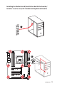
Installing a Processor/ Installation des Prozessors/ Installer un processeur/ Установка процессора 1 3 2 https://youtu.
Installing DDR4 memory/ Installation des DDR4-Speichers/ Installer une mémoire DDR4/ Установка памяти DDR4 http://youtu.
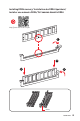
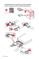
Connecting the Front Panel Header/ Anschließen der Frontpanel-Stiftleiste/ Connecter un connecteur du panneau avant/ Подключение разъемов передней панели http://youtu.
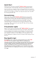
Installing the Motherboard/ Installation des Motherboards/ Installer la carte mère/ Установка материнской платы 1 2 Quick Start V
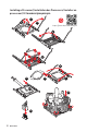
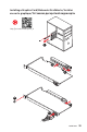
Installing SATA Drives/ Installation der SATA-Laufwerke/ Installer le disque dur SATA/ Установка дисков SATA 1 http://youtu.
Installing a Graphics Card/ Einbau der Grafikkarte/ Installer une carte graphique/ Установка дискретной видеокарты http://youtu.
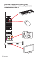
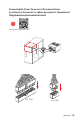
Connecting Peripheral Devices/ Peripheriegeräte/ Connecter un périphérique anschliessen/ Подключение периферийных устройств VIII Quick Start
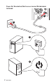
Connecting the Power Connectors/ Stromanschlüsse anschliessen/ Connecter les câbles du module d’alimentation/ Подключение разъемов питания http://youtu.
Power On/ Einschalten/ Mettre sous-tension/ Включение питания 1 2 3 4 X Quick Start
Contents Safety Information ................................................................................................. 3 Specifications......................................................................................................... 4 Rear I/O Panel ..................................................................................................... 10 LAN Port LED Status Table................................................................................... 10 Audio Ports Configuration ...
Hexadecimal Character Table .............................................................................. 35 Boot Phases .......................................................................................................... 35 Debug Code LED Table ......................................................................................... 35 ACPI States Codes ................................................................................................ 37 CPU Temperature ................................
Safety Information y The components included in this package are prone to damage from electrostatic discharge (ESD). Please adhere to the following instructions to ensure successful computer assembly. y Ensure that all components are securely connected. Loose connections may cause the computer to not recognize a component or fail to start. y Hold the motherboard by the edges to avoid touching sensitive components.
Specifications CPU y Supports Intel® Core™ X-Series Processor Family for LGA2066 Socket Chipset Intel® X299 Chipset y 8x DDR4 memory slots, support up to 128GB* y Quad channel memory architecture with the CPU that supports up to 4-channels DDR4** X-series processor support DDR4 4133(OC)/ 4000(OC)/ 3866(OC)/ 3800(OC)/ 3733(OC)/ 3600(OC)/ 3466(OC)/ 3400(OC)/ 3333(OC)/ 3200(OC)/ 3000(OC)/ 2933(OC)/ 2800(OC)/ 2667/ 2400/ 2133 MHz* Memory y Dual channel memory architecture with the CPU that supports up to
Continued from previous page Intel® X299 Chipset y 8x SATA 6Gb/s ports* y 2x M.2 slots (Key M)* Supports up to PCIe 3.0 x4 and SATA 6Gb/s M2_1 slot supports 2242/ 2260 /2280 storage devices M2_2 slot supports 2242/ 2260 /2280/ 22110 storage devices Storage Intel® Optane™ Memory Ready for all M.2 slots ** y 1x U.2 port *** Supports PCIe 3.0 x4 NVMe storage y Supports Intel® Smart Response Technology **** * M.2 slots and SATA ports share the same bandwidth. Please refer to page 23 for U.2, M.
Continued from previous page y 1x Clear CMOS button y 1x BIOS FLSAHBACK+ button y 1x PS/2 keyboard/ mouse combo port y 4x USB 2.0 Type-A ports Back Panel Connectors 1x BIOS FLASHBACK+ port y 4x USB 3.1 Gen1 Type-A ports y 2x LAN (RJ45) ports y 1x USB 3.1 Gen2 Type-A port y 1x USB 3.1 Gen2 Type-C port y 5x OFC audio jacks y 1x Optical S/PDIF OUT connector y 1x 24-pin ATX main power connector y 1x 8-pin ATX 12V power connector y 8x SATA 6Gb/s connectors y 2x USB 2.0 connectors (supports additional 4 USB 2.
Continued from previous page Debug LED y 1x 2-Digit Debug Code LED y Realtek® ALC1220 Codec Audio y 7.1-Channel High Definition Audio y Supports S/PDIF output I/O Controller NUVOTON NCT6795 Controller Chip y CPU/System temperature detection Hardware Monitor y CPU/System fan speed detection y CPU/System fan speed control Form Factor y ATX Form Factor y 12 in. x 9.6 in. (30.5 cm x 24.3 cm) y 2x 128 Mb flash BIOS Features y UEFI AMI BIOS y ACPI 6.0, PnP 1.0a, SM BIOS 3.
Continued from previous page y Audio Audio Boost 4 y Network Intel LAN with Network Manager Dual LAN y Storage Turbo U.2 Twin Turbo M.2 y Fan Pump Fan Smart Fan Control y LED Mystic Light Special Features Mystic Light Extension Mystic light SYNC EZ DEBUG LED y Protection M.2 Shield PCI-E Steel Armor U.
Continued from previous page y Stability Military Class 6 7000+ Quality Test y VR VR Ready Special Features y BIOS Click BIOS 5 BIOS FLASHBACK+ Dual BIOS y Certification Quadro SLI Ready Quadro Ready Specifications 9
Rear I/O Panel PS/2 Audio Ports LAN Clear CMOS BIOS FLSAHBACK+ button Optical S/PDIF-Out USB 2.0 USB 3.1 Gen2 Type-C USB 3.1 Gen1 USB 3.1 Gen2 Type-A USB 2.0/ BIOS FLASHBACK+ port y Clear CMOS button - Power off your computer. Press and hold the Clear CMOS button for about 5-10 seconds to reset BIOS to default values. y BIOS FLASHBACK+ port/ button - Please refer to page 41 for Updating BIOS with BIOS FLASHBACK+.
Realtek HD Audio Manager After installing the Realtek HD Audio driver, the Realtek HD Audio Manager icon will appear in the system tray. Double click on the icon to launch. Device Selection Advanced Settings Jack Status Application Enhancement Main Volume Connector Settings Profiles y Device Selection - allows you to select a audio output source to change the related options. The check sign indicates the devices as default.
Audio jacks to headphone and microphone diagram Audio jacks to stereo speakers diagram AUDIO INPUT Audio jacks to 7.
Overview of Components PUMP_FAN1 CPU_PWR1 SYS_FAN1 CPU_FAN1 CPU Socket DIMMA2 DIMMD1 DIMMD2 DIMMC1 DIMMC2 DIMMA1 DIMMB2 DIMMB1 ATX_PWR1 JUSB4 JUSB5 PCI_E1 JUSB3 M2_1 PCI_E2 SATA▼1▲2 PCI_E3 SATA▼3▲4 PCI_E4 SATA▼5▲6 M2_2 PCI_E5 U2_1 BIOS_SW1 SATA7 SATA8 PCI_E6 JPWRLED1 JLED1 SYS_FAN2 SYS_FAN3 JAUD1 VRAID1 JFP2 JUSB2 JTBT1 SYS_FAN4 JUSB1 JTPM1 JCI1 POWER1 RESET1 JBAT1 JFP1 Overview of Components 13
CPU Socket Introduction to the LGA 2066 CPU The surface of the LGA2066 CPU has four alignment keys and a yellow triangle to assist in correctly lining up the CPU for motherboard placement. The yellow triangle is the Pin 1 indicator. Important y Always unplug the power cord from the power outlet before installing or removing the CPU. y Please retain the CPU protective cap after installing the processor.
DIMM Slots S/K LED : S/K LED indicates that the installed CPU supports either 4-channels or 2-channels memory architecture.
DIMMD1 DIMMA1 DIMMA1 DIMMB1 DIMMA2 DIMMA1 DIMMB1 DIMMC1 DIMMD1 DIMMC1 DIMMC2 DIMMB1 DIMMA2 DIMMA1 DIMMB2 DIMMB1 DIMMC1 DIMMD1 DIMMD2 DIMMC1 DIMMC2 Important y Always insert a memory module in the DIMMC1 slot first. y To ensure system stability for Dual/ Triple/ Quad channel mode, memory modules must be of the same type, number and density. And for every channel, the odd number DIMM slot must to be installed first.
Memory module installation recommendation (2-Channels architecture CPU ) B1 B2 A1 A2 Intel Core X-series CPU C2 C1 D2 D1 1 DIMM 2 DIMMs Supports 2-channels memory architecture 3 DIMMs 4 DIMMs DIMMB1, B2, A1 and A2 are un-available DIMMD1 DIMMC1 DIMMD1 DIMMC1 DIMMC2 DIMMC1 DIMMD1 DIMMD2 DIMMC1 DIMMC2 Overview of Components 17
PCI_E1~6: PCIe Expansion Slots PCI_E1: PCIe 3.0 x16 (CPU lanes) PCI_E2: PCIe 3.0 x1 (PCH lanes) PCI_E3: PCIe 3.0 x4 (PCH lanes) PCI_E4: PCIe 3.0 x16 (CPU lanes) PCI_E5: PCIe 3.0 x1 (PCH lanes) PCI_E6: PCIe 3.0 x8 (CPU lanes) PCIe slots bandwidth table for 44-lane CPU Graphics Card Single 2-Way* 2-Way 3-Way PCI_E1 @ 3.0 x16 @ 3.0 x16 @ 3.0 x16 @ 3.0 x16 PCI_E2 3.0 x1 3.0 x1 3.0 x1 3.0 x1 PCI_E3 3.0 x4 3.0 x4 3.0 x4 3.0 x4 @ 3.0 x16 PCI_E4 3.0 x16 @ 3.0 x16 3.0 x16 PCI_E5 3.0 x1 3.
Multiple graphics cards installation recommendation PCI_E1 PCI_E1 PCI_E4 For 44 & 28 lanes CPUs PCI_E1 PCI_E4 PCI_E6 Important If you install a large and heavy graphics card, you need to use a tool such as MSI Gaming Series Graphics Card Bolster to support its weight and to prevent deformation of the slot.
Important y For a single PCIe x16 expansion card installation with optimum performance, using the PCI_E1 slot is recommended. y When adding or removing expansion cards, always turn off the power supply and unplug the power supply power cable from the power outlet. Read the expansion card’s documentation to check for any necessary additional hardware or software changes.
U2_1: U.2 Connector This connector is a U.2 interface port. Each connector can connect to one PCIe 3.0 x4 NVMe storage device. Video Demonstration Watch the video to learn how to Install U.2 SSD. http://youtu.be/KgFvKDxymvw Installing U.2 SSD 1. Connect the U.2 cable to the U.2 connector on the motherboard. 2. Connect the U.2 cable to the U.2 SSD. 3. Connect the U.2 cable to power adapter cable. U.2 SSD 2 U.2 Connector U.
M2_1~2: M.2 Slots (Key M) Important y Intel® RST only supports PCIe M.2 SSD with UEFI ROM. y Intel® Optane™ Memory Ready for all M.2 slots. Video Demonstration Watch the video to learn how to Install M.2 module. M2_1 M2_2 http://youtu.be/JCTFABytrYA Installing M.2 module 1. Remove the screw from the base screw. 2. Remove the base screw. 3. Tighten the base screw into the hole of the distance to the M.2 slot as the length your M.2 module. 5. Put the screw in the notch on the trailing edge of your M.
SATA1~8: SATA 6Gb/s Connectors These connectors are SATA 6Gb/s interface ports. Each connector can connect to one SATA device. SATA6 SATA5 SATA2 SATA1 SATA4 SATA3 SATA7 SATA8 Important y Please do not fold the SATA cable at a 90-degree angle. Data loss may result during transmission otherwise. y SATA cables have identical plugs on either sides of the cable. However, it is recommended that the flat connector be connected to the motherboard for space saving purposes. M.2, SATA & U.
M.2 slots with examples of various combination possibilities SATA7 SATA7 SATA8 SATA8 SATA3 SATA1 SATA4 SATA2 SATA6 SATA4 SATA2 2xM.2 SATA SSDs + 6xSATA HDDs + 1xPCI_E3 device 2xM.2 PCIe SSDs + 4xSATA HDDs + 1xU.2 SSD M.2 SATA PCI_E3 M.2 PCIe M.2 SATA U.2 M.2 PCIe SATA7 SATA8 JFP1, JFP2: Front Panel Connectors These connectors connect to the switches and LEDs on the front panel. 2 10 1 9 JFP1 1 JFP2 24 Overview of Components SATA3 SATA1 U.2 M.
CPU_PWR1, ATX_PWR1: Power Connectors These connectors allow you to connect an ATX power supply. 8 4 12 24 ATX_PWR1 1 13 5 1 CPU_PWR1 1 Ground 5 +12V 2 Ground 6 +12V 3 Ground 7 +12V 4 Ground 8 +12V 1 +3.3V 13 2 +3.3V 14 +3.3V -12V 3 Ground 15 Ground 4 +5V 16 PS-ON# 5 Ground 17 Ground 6 +5V 18 Ground 7 Ground 19 Ground 8 PWR OK 20 Res 9 5VSB 21 +5V 10 +12V 22 +5V 11 +12V 23 +5V 12 +3.
JUSB1~2: USB 2.0 Connectors These connectors allow you to connect USB 2.0 ports on the front panel. 2 10 1 9 1 VCC 2 VCC 3 USB0- 4 USB1- 5 USB0+ 6 USB1+ 7 Ground 8 Ground 9 No Pin 10 NC Important y Note that the VCC and Ground pins must be connected correctly to avoid possible damage. y In order to recharge your iPad,iPhone and iPod through USB ports, please install MSI® SUPER CHARGER utility. JUSB3~4: USB 3.1 Gen1 Connectors These connectors allow you to connect USB 3.
Charger Port The JUSB4 connector is a charger port which can increase USB power output for fast charging your smartphone or USB-powered devices. The Charger Port is hardware controlled by motherboard chip, it can still charge your device in suspend, hibernate state or even shutdown states. However, when you boot the computer into Windows®, you will need to install the MSI® SUPER CHARGER application to turn ON/OFF the Charging mode.
CPU_FAN1, PUMP_FAN1, SYS_FAN1~4: Fan Connectors Fan connectors can be classified as PWM (Pulse Width Modulation) Mode or DC Mode. PWM Mode fan connectors provide constant 12V output and adjust fan speed with speed control signal. DC Mode fan connectors control fan speed by changing voltage. When you plug a 3-pin (Non-PWM) fan to a fan connector in PWM mode, the fan speed will always maintain at 100%, which might create a lot of noise.
JAUD1: Front Audio Connector This connector allows you to connect audio jacks on the front panel. 2 10 1 9 1 MIC L 2 Ground 3 MIC R 4 NC MIC Detection 5 Head Phone R 6 7 SENSE_SEND 8 No Pin 9 Head Phone L 10 Head Phone Detection JCI1: Chassis Intrusion Connector This connector allows you to connect the chassis intrusion switch cable. Normal (default) Trigger the chassis intrusion event Using chassis intrusion detector 1.
JTPM1: TPM Module Connector This connector is for TPM (Trusted Platform Module). Please refer to the TPM security platform manual for more details and usages. 2 14 1 13 1 LPC Clock 2 3V Standby power 3 LPC Reset 4 3.
BIOS_SW1: Multi-BIOS Switch This motherboard has two built-in BIOS ROMs (Labeled A and B, default BIOS ROM is A). If one is crashed, you can shift to the other for booting by sliding the switch. BIOS A (Default) BIOS B Recovering BIOS When BIOS updating fails or causes the computer non-bootable, you can recover the failed BIOS by the steps below. Before recovering, please download the latest BIOS file that matches your motherboard model from MSI website.
POWER1, RESET1: Power Button, Reset Button The Power / Reset button allows you to power on / reset the computer. Power button Reset button JLED1: RGB LED connector These connectors allow you to connect the 5050 RGB LED strips. 1 1 +12V 2 G 3 R 4 B 1 Extension cable 5050 LED strip JLED1 Important y This connector supports 5050 RGB multi-color LED strips (12V/G/R/B) with the maximum power rating of 3A (12V). Please keeping the LED strip shorter than 2 meters to prevent dimming.
Onboard LEDs EZ Debug LED These LEDs indicate the debug status of the motherboard. CPU - indicates CPU is not detected or fail. DRAM - indicates DRAM is not detected or fail. VGA - indicates GPU is not detected or fail. BOOT - indicates the booting device is not detected or fail. PCIe x16 slot LEDs These LED indicate the PCIe x16 slots status.
Fan LEDs These LEDs indicate the fan control mode. CPU_FAN1 LED PUMP_FAN1 LED LED Color Fan control mode Red PWM mode Green DC mode Multi-BIOS LEDs Multi-BIOS LEDs indicate which BIOS is in operation. BIOS B LED (White) BIOS A LED (Red) JPWRLED1: LED light demonstration power input connector This connector is used by retailers to demonstrate onboard LED lights.
Debug Code LED The Debug Code LED displays progress and error codes during and after POST. Refer to the Debug Code LED table for details.
Memory initialization. Memory presence detection 60 DXE Core is started 2D Memory initialization. Programming memory timing information 61 NVRAM initialization Installation of the PCH Runtime Services 2E Memory initialization. Configuring memory 62 63 CPU DXE initialization is started 2F Memory initialization (other) 31 Memory Installed 32 CPU post-memory initialization is started 33 CPU post-memory initialization. Cache initialization 34 CPU post-memory initialization.
A8 Setup Verifying Password E9 S3 Resume PPI not Found A9 Start of Setup EA S3 Resume Boot Script Error AB Setup Input Wait EB S3 OS Wake Error AD Ready To Boot event AE Legacy Boot event AF Exit Boot Services event B0 Runtime Set Virtual Address MAP Begin B1 Runtime Set Virtual Address MAP End B2 EC - EF Reserved for future AMI error codes Recovery Progress Codes F0 Recovery condition triggered by firmware (Auto recovery) Legacy Option ROM Initialization F1 Recovery condition t
Updating LED Firmware Updating the LED firmware can help improve lighting effect. To update LED firmware: 1. Install and launch MSI LIVE UPDATE 6. 2. Select BIOS Update. 3. Click on Scan button. If the LED firmware needs to be updated, the version of the firmware will appear in the list. 4. Select the item in the list. 5. Click on Total installer button to download and install the firmware. 6. When the process is 100% completed, you need to restart your computer to enable the LED firmware.
BIOS Setup The default settings offer the optimal performance for system stability in normal conditions. You should always keep the default settings to avoid possible system damage or failure booting unless you are familiar with BIOS. Important y BIOS items are continuously update for better system performance. Therefore, the description may be slightly different from the latest BIOS and should be for reference only. You could also refer to the HELP information panel for BIOS item description.
Resetting BIOS You might need to restore the default BIOS setting to solve certain problems. There are several ways to reset BIOS: y Go to BIOS and press F6 to load optimized defaults. y Short the Clear CMOS jumper on the motherboard. Important Be sure the computer is off before clearing CMOS data. Please refer to the Clear CMOS jumper section for resetting BIOS.
Updating BIOS with BIOS FLASHBACK+ Before updating: Please download the latest BIOS file that matches your motherboard model from MSI® website and rename the BIOS file to MSI.ROM. And then, save the MSI.ROM file to the root of USB flash drive. Important Only the FAT32 format USB flash drive supports updating BIOS by BIOS FLASHBACK+. 1. Connect power supply to CPU_PWR1 and ATX_PWR1. (No other components are necessary but power supply.) 2. Plug the USB flash drive that contains the MSI.
EZ Mode At EZ mode, it provides the basic system information and allows you to configure the basic setting. To configure the advanced BIOS settings, please enter the Advanced Mode by pressing the Setup Mode switch or F7 function key. XMP switch Setup Mode switch Screenshot Search Language System information OC GENIE 4 switch Boot device priority bar Information display M-Flash Favorites Hardware Monitor Function buttons y OC GENIE 4 switch - click on it to toggle the OC GENIE 4 for OC.
y Information display - click on the CPU, Memory, Storage, Fan Info and Help buttons on left side to display related information. y Function buttons - enable or disable the LAN Option ROM, M.2/Optane Genie, Hardcore Mode, AHCI, RAID, CPU Fan Fail Warning Control and BIOS Log Review by clicking on their respective button. Hardcore Mode - always keep the CPU in full speed mode to maximize system performance. This feature will increase power consumption.
Advanced Mode Press Setup Mode switch or F7 function key can switch between EZ Mode and Advanced Mode in BIOS setup. XMP switch Setup Mode switch Screenshot Search Language System information OC GENIE 4 switch Boot device priority bar BIOS menu selection BIOS menu selection Menu display y OC GENIE 4 switch/ XMP switch/ Setup Mode switch/ Screenshot/ Language/ System information/ Boot device priority bar - please refer to the descriptions of EZ Mode Overview section.
OC Menu This menu is for advanced users who want to overclock the motherboard. Important y Overclocking your PC manually is only recommended for advanced users. y Overclocking is not guaranteed, and if done improperly, it could void your warranty or severely damage your hardware. y If you are unfamiliar with overclocking, we advise you to use GAME BOOST function for easy overclocking. f OC Explore Mode [Normal] Enables or disables to show the normal or expert version of OC settings.
f CPU Ratio Mode [Dynamic Mode]* Selects the CPU Ratio operating mode. This item will appear when you set the CPU ratio manually. [Fixed Mode] Fixes the CPU ratio. [Dynamic Mode] CPU ratio will be changed dynamically according to the CPU loading. f CPU Ratio Offset When Running AVX [Auto] Sets a offset value to lower the CPU core ratio. It could be helpful for heat dissipation when running AVX instruction set. If set to Auto, BIOS will configure this setting automatically.
f DRAM Frequency [Auto] Sets the DRAM frequency. Please note the overclocking behavior is not guaranteed. f Adjusted DRAM Frequency Shows the adjusted DRAM frequency. Read-only. f DRAM Timing Mode [Link] Selects the memory timing mode. [Link] Allows user to configure the DRAM timing for all memory channel. [UnLink] Allows user to configure the DRAM timing for respective memory channel. f Advanced DRAM Configuration Press Enter to enter the sub-menu.
f CPU Memory Changed Detect [Enabled]* Enables or disables the system to issue a warning message during boot when the CPU or memory has been replaced. [Enabled] The system will issue a warning message during boot and than needs to load the default settings for new devices. [Disabled] Disables this function and keeps the current BIOS settings. f CPU Specifications Press Enter to enter the sub-menu. This sub-menu displays the information of installed CPU.
fHardware Prefetcher [Enabled] Enables or disables the hardware prefetcher (MLC Streamer prefetcher). [Enabled] Allows the hardware prefetcher to automatically pre-fetch data and instructions into L2 cache from memory for tuning the CPU performance. [Disabled] Disables the hardware prefetcher. fAdjacent Cache Line Prefetch [Enabled] Enables or disables the CPU hardware prefetcher (MLC Spatial prefetcher).
fLong Duration Maintained (s) [Auto] Sets the maintaining time for Long duration power Limit(W). fShort Duration Power Limit (W) [Auto] Sets the short duration TDP power limit for CPU in Turbo Boost mode. fCPU Current Limit (A) [Auto] Sets maximum current limit of CPU package in Turbo Boost mode. When the current is over the specified value, the CPU will automatically reduce the core frequency for reducing the current.
Software Description Installing Windows® 10 1. Power on the computer. 2. Insert the Windows® 10 disc into your optical drive. 3. Press the Restart button on the computer case. 4. Press F11 key during the computer POST (Power-On Self Test) to get into Boot Menu. 5. Select your optical drive from the Boot Menu. 6. Press any key when screen shows Press any key to boot from CD or DVD... message. 7. Follow the instructions on the screen to install Windows® 10. Installing Drivers 1.
NOTE 52 Software Description
Inhalt Sicherheitshinweis ................................................................................................ 3 Spezifikationen ...................................................................................................... 4 Rückseite E/A ...................................................................................................... 11 LAN Port LED Zustandstabelle ............................................................................ 11 Konfiguration der Audioanschlüsse ...
Hexadezimalzeichen ............................................................................................. 36 Boot-Phasen ......................................................................................................... 36 Debug-Code-LED-Tabelle .................................................................................... 36 ACPI Status-Codes ............................................................................................... 39 CPU-Temperatur ................................
Sicherheitshinweis y Die im Paket enthaltene Komponenten sind der Beschädigung durch elektrostatischen Entladung (ESD). Beachten Sie bitte die folgenden Hinweise, um die erfolgreichen Computermontage sicherzustellen. y Stellen Sie sicher, dass alle Komponenten fest angeschlossen sind. Lockere Steckverbindungen können Probleme verursachen, zum Beispiel: Der Computer erkennt eine Komponente nicht oder startet nicht.
Spezifikationen CPU y Unterstützt Intel® Core™ X-Serie Processoren für LGA2066 Sockel Chipsatz Intel® X299 Chipsatz y 8x DDR4 Speicherplätze, aufrüstbar bis 128GB* y Die 4-Kanal-Speicherarchitektur für Prozessoren mit 4-Kanal DDR4 Unterstützung** X-Serie Prozessoren unterstützen DDR4 4133(OC)/ 4000(OC)/ 3866(OC)/ 3800(OC)/ 3733(OC)/ 3600(OC)/ 3466(OC)/ 3400(OC)/ 3333(OC)/ 3200(OC)/ 3000(OC)/ 2933(OC)/ 2800(OC)/ 2667/ 2400/ 2133 MHz* Speicher y Die 2-Kanal-Speicherarchitektur für Prozessoren mit 2-Kan
Fortsetzung der vorherigen Seite Intel® X299 Chipsatz y 8x SATA 6Gb/s Anschlüsse* y 2x M.2 Steckplätze (Key M)* Unterstützt bis zu PCIe 3.0 x4 und SATA 6Gb/s Der M2_1 Steckplatz unterstützt die 2242/ 2260 /2280 Speichergeräte Der M2_2 Steckplatz unterstützt die 2242/ 2260 /2280/ 22110 Speichergeräte Aufbewahrung Intel® Optane™ Technik unterstützt alle M.2 Steckplätze ** y 1x U.2 Anschluss *** Unterstützt PCIe 3.0 x4 NVMe Aufbewahrung y Unterstützt Intel® Smart Response Technologie **** * Die M.
Fortsetzung der vorherigen Seite y ASMedia® ASM3142 Chipsatz 3x USB 3.1 Gen2 (SuperSpeed USB 10Gbps) Anschlüsse (1 Typ-A Anschluss und 1 Typ-C Anschluss an der rückseitigen Anschlussleiste, 1 Typ-C Anschluss steht durch die internen USB Anschluss zur Verfügung) y ASMedia® ASM1074 Hub USB 3x USB 3.1 Gen1 (SuperSpeed USB) Anschlüsse an der rückseitigen Anschlussleiste y Intel® X299 Chipsatz 5x USB 3.
Fortsetzung der vorherigen Seite y 1x 24-poliger ATX Stromanschluss y 1x 8-poliger ATX12V Stromanschluss y 8x SATA 6Gb/s Anschlüsse y 2x USB 2.0 Anschlüsse (unterstützt zusätzliche 4 USB 2.0-Ports) y 2x USB 3.1 Gen1 Anschlüsse (unterstützt zusätzliche 4 USB 3.1 Gen1-Ports) y 1x USB 3.
Fortsetzung der vorherigen Seite y 2x 128 Mb Flash BIOS Funktionen y UEFI AMI BIOS y ACPI 6.0, PnP 1.0a, SM BIOS 3.
Fortsetzung der vorherigen Seite y Audio Audio Boost 4 y Netzwerk Intel LAN mit Network Manager Dual-LAN y Speicherung Turbo U.2 Twin Turbo M.2 y Lüfter Pump-Lüfter Smart-Lüftersteuerung y LED Mystic Light Besondere Funktionen Mystic Light Extension Mystic Light SYNC EZ DEBUG LED y Schutz M.2-Abdeckung PCI-E Steel Armor U.
Fortsetzung der vorherigen Seite y Stabilität Military Class 6 7000+ Quality Test y VR VR Ready Besondere Funktionen y BIOS Click BIOS 5 BIOS FLASHBACK+ Dual BIOS y Zertifizierung Quadro SLI Ready Quadro Ready 10 Spezifikationen
Rückseite E/A LAN PS/2 Audioanschlüsse Clear CMOS BIOS FLSAHBACK+ Taste USB 2.0 Optischer S/PDIFAusgang USB 3.1 Gen2 Typ-C USB 3.1 Gen2 Typ-A USB 3.1 Gen1 USB 2.0/ BIOS FLASHBACK+ Anschluss y Clear CMOS Taste - Schalten Sie den Computer aus. Halten Sie die Taste „Clear CMOS“ für 5-10 Sekunden gedrückt, um das BIOS auf die Standardwerte zurückzusetzen. y BIOS FLASHBACK+ Anschluss/ Taste - Auf der Seite 43 finden Sie eine Anleitung für eine BIOS-Aktualisierung per BIOS FLASHBACK+.
Realtek HD Audio Manager Nach der Installation des Realtek HD Audio-Treibers, wird das Symbol Realtek HD Audio Manager in der Taskleiste angezeigt. Klicken Sie doppelt auf dieses Symbol, um das Programm zu starten. Geräteauswahl Erweiterte Einstellungen Verbindungsstatus Optimierungen Lautstärke Anschlüsse Profil y Geräteauswahl - Ermöglicht die Auswahl der Audio-Ausgangs Quelle. Das aktuell aktivierte Gerät ist mit einem Haken gekennzeichnet.
Audiobuchsen für den Anschluss von einem Kopfhörer und Mikrofon Audiobuchsen für Stereo-Lautsprecher AUDIO INPUT Audiobuchsen für 7,1 Kanal Anlage AUDIO INPUT Rear Front Side Center/ Subwoofer Rückseite E/A 13
Übersicht der Komponenten PUMP_FAN1 CPU_PWR1 SYS_FAN1 CPU_FAN1 CPU Sockel DIMMA2 DIMMD1 DIMMD2 DIMMC1 DIMMC2 DIMMA1 DIMMB2 DIMMB1 ATX_PWR1 JUSB4 JUSB5 PCI_E1 JUSB3 M2_1 PCI_E2 SATA▼1▲2 PCI_E3 SATA▼3▲4 PCI_E4 SATA▼5▲6 M2_2 PCI_E5 U2_1 BIOS_SW1 SATA7 SATA8 PCI_E6 JPWRLED1 JLED1 SYS_FAN2 SYS_FAN3 JAUD1 14 Übersicht der Komponenten VRAID1 JFP2 JUSB2 JTBT1 SYS_FAN4 JUSB1 JTPM1 JCI1 POWER1 RESET1 JBAT1 JFP1
CPU Sockel Erklärung zur LGA 2066 CPU Die Obserseite der LGA 2066 CPU hat vier Justierungen und ein gelbes Dreieck um die korrekte Ausrichtung der CPU auf dem Motherboard zu gewährleisten. Das gelbe Dreieck des Prozessors definiert die Position des ersten Pins. Wichtig y Ziehen Sie das Netzkabel ab, bevor Sie die CPU ein- und ausbauen. y Bitte bewahren Sie die CPU Schutzkappe nach der Installation des Prozessors auf.
DIMM-Steckplätze S/K LED : Die S/K LED zeigt an ob die installierte CPU 4-Kanaloder 2-Kanal-Speicherarchitektur unterstützt.
DIMMD1 DIMMA1 DIMMA1 DIMMB1 DIMMA2 DIMMA1 DIMMB1 DIMMC1 DIMMD1 DIMMC1 DIMMC2 DIMMC1 DIMMB1 DIMMA2 DIMMA1 DIMMB2 DIMMB1 DIMMD1 DIMMD2 DIMMC1 DIMMC2 Wichtig y Um einen sicheren Systemstart zu gewährleisten, bestücken Sie immer DIMMC1 zuerst. y Stellen Sie im Dual-/ Triple-/ Quad-Kanal-Modus bitte sicher, dass Sie Module des gleichen Typs und identischer Speicherdichte in den DIMM Slots unterschiedlicher Kanäle verwenden.
Speichermodul-Installationsempfehlung (2-Kanal CPU-Architektur) B1 B2 A1 A2 Intel Core X-Serie CPU C2 C1 D2 D1 1 DIMM 2 DIMMs Unterstützt 2-Kanal Speicherarchitektur 3 DIMMs 4 DIMMs DIMMB1, B2, A1 und A2 sind nicht verfügbar DIMMD1 DIMMC1 DIMMD1 DIMMC1 DIMMC2 18 Übersicht der Komponenten DIMMC1 DIMMD1 DIMMD2 DIMMC1 DIMMC2
PCI_E1~6: PCIe Erweiterungssteckplätze PCI_E1: PCIe 3.0 x16 (CPU Lanes) PCI_E2: PCIe 3.0 x1 (PCH Lanes) PCI_E3: PCIe 3.0 x4 (PCH Lanes) PCI_E4: PCIe 3.0 x16 (CPU Lanes) PCI_E5: PCIe 3.0 x1 (PCH Lanes) PCI_E6: PCIe 3.0 x8 (CPU Lanes) Tabelle der PCIe Bandbreiten Für 44-Lane CPU Graphikkarte Einzel 2-Wege* 2-Wege 3-Wege PCI_E1 @ 3.0 x16 @ 3.0 x16 @ 3.0 x16 @ 3.0 x16 PCI_E2 3.0 x1 3.0 x1 3.0 x1 3.0 x1 PCI_E3 3.0 x4 3.0 x4 3.0 x4 3.0 x4 @ 3.0 x16 PCI_E4 3.0 x16 @ 3.0 x16 3.
Mehrere Grafikkarten Einbauempfehlung PCI_E1 PCI_E1 PCI_E4 Für 44- & 28-Lanes CPU PCI_E1 PCI_E4 PCI_E6 Wichtig Wenn Sie eine große und schwere Grafikkarte einbauen, benötigen Sie einen Grafikkarten-Stabilisator (Graphics Card Bolster) der das Gewicht trägt und eine Verformung des Steckplatzes vermeidet.
Wichtig y Für die Installation einer einzelnen PCIe x16 Erweiterungskarte mit optimaler Leistung, empfehlen wir den PCI_E1 Steckplatz zu verwenden. y Achten Sie darauf, dass Sie den Strom abschalten und das Netzkabel aus der Steckdose herausziehen, bevor Sie eine Erweiterungskarte installieren oder entfernen. Lesen Sie bitte auch die Dokumentation der Erweiterungskarte, um notwendige zusätzliche Hardware oder Software-Änderungen zu überprüfen.
U2_1: U.2 Anschluss Dieser Anschluss ist ein U.2 Schnittstellenmodul. Pro Anschluss kann ein PCIe 3.0 x4 NVMe Speichergerät angeschlossen werden. Video-Demonstration Eine anschauliche Darstellung zur Installation einer U.2 SSD finden Sie im Video: http://youtu.be/KgFvKDxymvw Installation einer U.2 SSD 1. Schließen Sie das U.2-Kabel an die U.2Steckverbindung des Motherboards an. 2. Schließen Sie das U.2-Kabel an der U.2 SSD an. 3. Schließen Sie das U.2-Kabel an das Netzkabel an. U.2 SSD 2 U.
M2_1~2: M.2 Steckplätze (Key M) Wichtig y Intel® RST unterstützt nur PCIe M.2 SSD mit UEFI ROM. y Intel® Optane™ Technik unterstützt alle M.2 Steckplätze. Video-Demonstration Eine anschauliche Darstellung zur Installation eines M.2 Moduls finden Sie im Video. M2_1 M2_2 http://youtu.be/JCTFABytrYA Installation eines M.2 Moduls 1. Schraubsockel. 2. Entfernen Sie den Schraubsockel. 3. Befestigen Sie den Schraubsockel in dem Loch, welches zur Länge des M.2 Moduls passt. 5.
SATA1~8: SATA 6Gb/s Anschlüsse Dieser Anschluss basiert auf der Hochgeschwindigkeitsschnittstelle SATA 6Gb/s. Pro Anschluss kann ein SATA Gerät angeschlossen werden. SATA6 SATA5 SATA2 SATA1 SATA4 SATA3 SATA7 SATA8 Wichtig y Knicken Sie das SATA-Kabel nicht in einem 90° Winkel. Datenverlust könnte die Folge sein. y SATA-Kabel haben identische Stecker an beiden Enden. Es wird empfohlen den flachen Stecker auf dem Motherboard einstecken. Tabelle der U.2-, M.
M.2 Steckplätze mit Beispielen zu den verschiedenen Kombinationsmöglichkeiten SATA7 SATA7 SATA8 SATA8 SATA4 SATA2 SATA3 SATA1 SATA6 SATA4 SATA2 2xM.2 SATA SSDs + 6xSATA HDDs + 1xPCI_E3 Gerät 2xM.2 PCIe SSDs + 4xSATA HDDs + 1xU.2 SSD M.2 SATA PCI_E3 M.2 PCIe M.2 SATA U.2 M.2 PCIe SATA3 SATA1 U.2 M.2 SATA SATA3 SATA6 SATA4 SATA2 SATA5 SATA3 SATA1 M.2 PCIe U.2 M.2 PCIe SATA6 SATA4 SATA2 1xM.2 PCIe SSD + 1xM.2 SATA SSD +7xSATA HDDs + 1xU.2 SSD 1xM.2 PCIe SSD + 8xSATA HDDs + 1xU.
CPU_PWR1, ATX_PWR1: Stromanschlüsse Mit diesen Anschlüssen verbinden Sie die ATX Stromstecker. 8 4 12 24 ATX_PWR1 1 13 5 1 CPU_PWR1 1 Ground 5 +12V 2 Ground 6 +12V 3 Ground 7 +12V 4 Ground 8 +12V 1 +3.3V 13 2 +3.3V 14 +3.3V -12V 3 Ground 15 Ground 4 +5V 16 PS-ON# 5 Ground 17 Ground 6 +5V 18 Ground 7 Ground 19 Ground 8 PWR OK 20 Res 9 5VSB 21 +5V 10 +12V 22 +5V 11 +12V 23 +5V 12 +3.
JUSB1~2: USB 2.0 Anschlüsse Mit diesen Anschlüssen können Sie die USB 2.0 Anschlüsse auf dem Frontpanel verbinden. 2 10 1 9 1 VCC 2 VCC 3 USB0- 4 USB1- 5 USB0+ 6 USB1+ 7 Ground 8 Ground 9 No Pin 10 NC Wichtig y Bitte beachten Sie, dass Sie die mit VCC (Stromführende Leitung) und Ground (Erdleitung) bezeichneten Pins korrekt verbinden müssen, ansonsten kann es zu Schäden kommen.
Ladegerätanschluss Der JUSB4 Anschluss ist ein Ladegerätanschluss, mit dem Sie die Ladegeschwindigkeit Ihres Smartphones oder anderen USB-betriebenen Geräten erhöhen. Der Ladegerätanschluss ist eine vom Mainboard-Chip gesteuerte Hardware, die auch im Ruhezustand, Standby- oder im ausgeschalteten Modus Geräte aufladen kann. Wenn Sie den Computer in Windows® starten, müssen Sie die MSI® SUPER CHARGER Anwendung installieren, um den Lademodus EIN/AUSZUSCHALTEN.
CPU_FAN1, PUMP_FAN1, SYS_FAN1~4: Stromanschlüsse für Lüfter Diese Anschlüsse können im PWM (Pulse Width Modulation) Modus oder Spannungsmodus betrieben werden. Im PWM-Modus bieten die Lüfteranschlüsse konstante 12V Ausgang und regeln die Lüftergeschwindigkeit per Drehzahlsteuersignal. Im DC-Modus bestimmen die Lüfteranschlüsse die Lüftergeschwindigkeit durch Ändern der Spannung.
JAUD1: Audioanschluss des Frontpanels Dieser Anschluss ermöglicht den Anschluss von Audiobuchsen eines Frontpanels. 2 10 1 9 1 MIC L 2 Ground 3 MIC R 4 NC MIC Detection 5 Head Phone R 6 7 SENSE_SEND 8 No Pin 9 Head Phone L 10 Head Phone Detection JCI1: Gehäusekontaktanschluss Dieser Anschluss wird mit einem Kontaktschalter verbunden. Normal (Standardwert) Löse den Gehäuseeingriff aus Gehäusekontakt-Detektor verwenden 1.
JTPM1: TPM Anschluss Dieser Anschluss wird für das TPM Modul (Trusted Platform Module) verwendet. Weitere Informationen über den Einsatz des optionalen TPM Modules entnehmen Sie bitte dem TPM Plattform Handbuch. 2 14 1 13 1 LPC Clock 2 3V Standby power 3 LPC Reset 4 3.
BIOS_SW1: Multi-BIOS Schalter Das Motherboard hat zwei eigebaute BIOS ROMs (bezeichnet als A und B, Standard ist BIOS ROM A). Falls ein BIOS abgestürzt ist, können Sie durch verschieben des Schalters zum zweiten BIOS umschalten um zu starten. BIOS A (Standardwert)) BIOS B BIOS wiederherstellen Wenn ein BIOS-Update fehlgeschlagen ist und das System nicht gestartet werden kann, können Sie die folgenden Schritte ausführen, um das BIOS wiederherzustellen.
POWER1, RESET1: Power-Taste, Reset-Taste Mit dieser Power-Taste können Sie den Computer einschalten. Mit der Reset-Taste können Sie den Computer zurücksetzen. Power-Taste Reset-Taste JLED1: RGB LED Anschluss Mit diesem Anschluss können Sie den 5050 RGB-LED-Streifen anschließen. 1 1 +12V 2 G 3 R 4 B 1 Verlängerungskabel 5050 LED Streifen JLED1 Wichtig y Dieser Anschluss unterstützt die 5050 RGB Mehr-Farb-LED-Streifen (12V/R/G/B) mit der maximalen Leistung von 3A (12V).
Onboard-LEDs EZ Debug LED Diese LEDs zeigen den Debug-Status des Motherboards an. CPU - CPU wird nicht erkannt oder ist fehlerhaft. DRAM - DRAM wird nicht erkannt oder ist fehlerhaft. VGA - GPU wird nicht erkannt oder ist fehlerhaft. BOOT - Boot-Gerät wird nicht erkannt oder ist fehlerhaft. PCIe x16 Steckplatz LEDs Die LED zeigen den Status der PCIe x16-Steckplätze an.
Lüfter LEDs Die LEDs zeigen den Lüftersteuerungsmodus an. CPU_FAN1 LED PUMP_FAN1 LED LED-Farbe Lüftersteuerungsmodus Rot PWM Modus Grün DC Modus Multi-BIOS LEDs Die Multi-BIOS LEDs zeigen an, welches BIOS in Betrieb ist. BIOS B LED (weiß) BIOS A LED (rot) JPWRLED1: Stromanschluss zur Demonstration des LEDLichteffekts Dieser Anschluss ermöglicht es dem Fachhändler die integrierten LED-Lichteffekte zu zeigen.
Debug-Code-LED Die Debug-Code-LED-Anzeige zeigt den Fortschritt und das Fehlercode während und nach dem POST-Vorgang an. Einzelheiten entnehmen Sie bitte der Debug-Code LEDTabelle.
1A - 1C Pre-Memory PCH- Initialisierung (PCHModul spezifisch) 2B Speicher-Initialisierung. Serial Presence Detect (SPD) liest die Daten aus 2C Speicher-Initialisierung. Speicher -Erfassung 2D Speicher-Initialisierung. Programmierung des Speicher-Timings 2E Speicher-Initialisierung. Konfiguration des Speichers 2F Speicher-Initialisierung (sonstige) 31 Speicher ist installiert 32 CPU Post-Memory-Initialisierung wird gestartet 33 CPU Post-Memory-Initialisierung.
97 Verbindung der KonsolenAusgangsgeräte 98 Verbindung der KonsolenEingangsgeräte 99 Super-IO-Initialisierung 9A USB-Initialisierung wird gestartet 9B USB-Rücksetzung 9C USB-Erkennung 9D USB-Aktivierung 9E -9F Reserviert für zukünftige AMI-Codes A0 IDE Initialisierung wird gestartet A1 IDE-Rücksetzung A2 IDE-Erkennung A3 IDE-Aktivierung A4 SCSI Initialisierung wird gestartet A5 SCSI-Rücksetzung A6 SCSI-Erkennung A7 SCSI-Aktivierung A8 Bereite Kennwortüberprüfung vor A9 Beg
Wiederherstellung Fehler-Codes F8 Wiederherstellung-PPI ist nicht verfügbar F9 Wiederherstellung-Kapsel ist nicht gefunden FA Ungültige Wiederherstellung-Kapsel FB - FF Reserviert für zukünftige AMIFehlercodes ACPI Status-Codes Nach dem Start erscheinen die folgende Codes und versetzen das Betriebssystem in den ACPI-Modus.
Aktualisierung der LED-Firmware Die Aktualisierung der LED-Firmware kann zur Verbesserung der Leuchteffekte beitragen. LED-Firmware-Aktualisierungsschritte: 1. Installieren und starten Sie „MSI LIVE UPDATE 6“. 2. Wählen Sie BIOS Update aus. 3. Klicken Sie auf die Scan Taste. Wenn die LED-Firmware veraltet ist, erscheint die neue Softwareversion in der Liste. 4. Wählen Sie den Eintrag in der Liste aus. 5.
BIOS-Setup Die Standardeinstellungen bieten die optimale Leistung für die Systemstabilität unter Normalbedingungen. Sie sollten immer die Standardeinstellungen behalten, um mögliche Schäden des Systems oder Boot-Fehler zu vermeiden, außer Sie besitzen ausreichende BIOS Kenntnisse. Wichtig y BIOS Funktionen werden für eine bessere Systemleistung kontinuierlich aktualisiert. Deswegen können die Beschreibungen leicht von der letzten Fassung des BIOS abweichen und sollten demnach nur als Anhaltspunkte dienen.
Reset des BIOS Sie können die Werkseinstellung wieder herstellen, um bestimmte Probleme zu lösen. Es gibt verschiedene Möglichkeiten, um das BIOS zurückzusetzen: y Öffnen Sie das BIOS und drücken Sie F6, um optimierten Einstellungen zu laden. y Schließen Sie die Clear CMOS Steckbrücke an das Motherboard an. Wichtig Bitte lesen Sie für Informationen zum BIOS-Reset im Bereich „Clear CMOS Steckbrücke“ nach.
Aktualisierung des BIOS mit BIOS FLASHBACK+ Vorbereitung: Laden Sie bitte die neueste BIOS Version, die das Modell des Motherboards entspricht, von der offiziellen MSI Website und benennen die BIOS-Datei im MSI.ROM um. Und speichern Sie die MSI.ROM-Datei im Root-Verzeichnis des USB-Flash-Speichers. Wichtig Nur USB-Flashlaufwerke im FAT32-Format unterstützen einen BIOS-Update per BIOS FLASHBACK+. 1. Verbinden Sie die Stromversorgung an dem CPU_PWR1- und ATX_PWR1-Stecker.
EZ Modus Im EZ-Modus können Sie die Grundinformationen des Systems einsehen und grundlegende Einstellungen konfigurieren. Um sich die erweiterten BIOSEinstellungen anzeigen zu lassen, aktivieren Sie bitte den Erweiterten Modus durch Drücken des Setup Modus Schalter oder der Funktionstaste F7.
y Informationsanzeige - Klicken Sie auf die Schaltfläche CPU, Memory, Storage, Fan Info und Help auf der linken Seite, um die jeweiligen Informationen anzuzeigen. y Funktionstasten - Aktivieren oder deaktivieren Sie LAN Option ROM, M.2/Optane Genie, Hardcore Mode, AHCI, RAID, CPU Fan Fail Warning Control und BIOS Log Review durch Anklicken der zugehörigen Schaltfläche. Hardcore-Modus - Im Hardcore-Modus behält die CPU die volle Geschwindigkeit bei um die Systemleistung zu maximieren.
Erweiterter Modus Drücken Sie den Setup Modus Schalter oder die Funkionstaste F7, um zwischen dem EZ-Modus und Erweiterten-Modus im BIOS-Setup zu wechseln.
OC Menü In diesem Menü können Benutzer das BIOS anpassen und das Mainboard übertakten. Bitte führen Sie nur Änderungen durch, wenn Sie sich über das Ergebnis im Klaren sind. Sie sollten Erfahrung beim Übertakten haben, da Sie sonst das Motherboard oder Komponenten des Systems beschädigen können. Wichtig y Die Übertaktung ist nur für fortgeschrittene Benutzer zu empfehlen. y Eine erfolgreiche Übertaktung ist nicht gewährleistet.
f Adjusted CPU Frequency Zeigt die eingestellte Frequenz der CPU an. Es handelt sich um eine Anzeige – Änderungen sind nicht möglich. f CPU Ratio Mode [Dynamic Mode]* Wählen Sie den Betriebsmodus des CPU-Multiplikators. Diese Option wird angezeigt, wenn Sie den CPU-Multiplikator manuell einstellen. [Fixed Mode] [Dynamic Mode] Legt den CPU-Multiplikator fest. Der CPU-Multiplikator wird dynamisch je nach CPU-Belastung verändert.
f Extreme Memory Profile (X.M.P.) [Disabled] Extreme Memory Profile (XMP) basieren auf Zertifizierungen für Speichermodule aus dem PC-Bereich. Aktivieren Sie die Funktion XMP oder wählen Sie ein Profil des Speichermoduls zum Übertakten aus. Diese Option steht zur Verfügung, wenn die installierten Speichermodule die XMP Technik unterstützen. f DRAM Reference Clock [Auto]* Setzen Sie den DRAM-Referenztakt. Der erlaubte Wertebereich ist abhängig von der installierten CPU.
f VCCIN Voltage [Auto] Legen Sie die CPU Eingangsspannung fest. Die CPU Eingangsspannung ist die CPU Stromquelle, die durch Komponenten der CPU gemeinsam genutzt wird. f CPU Voltages control [Auto] Erlaubt das Einstellen der CPU-Spannungen. Wenn die Einstellung auf Auto gesetzt ist, wird das BIOS die Spannungen automatisch einstellen oder Sie können es manuell einstellen. f DRAM Voltages control [Auto] Erlaubt das Einstellen der DRAM-Spannungen.
fHyper-Threading [Enabled] ie Intel Hyper-Threading Technologie behandelt die Prozessorkerne innerhalb des Prozessors als multi-logische Prozessoren, die Anweisungen simultan durchführen können. Dadurch tritt eine wesentliche Verbesserung der Systemleistung ein. Diese Option wird angezeigt, wenn die installierte CPU diese Einstellungen unterstützt. [Enable] Aktiviert die Intel Hyper-Threading Technologie. [Disabled] Deaktiviert die Option, wenn das System die HT-Funktion nicht unterstützt.
fIntel C-State [Auto] Aktiviert oder deaktiviert das Intel C-State. C-State ist eine durch ACPI definierte Prozessor-Power-Management-Technologie. [Auto] Diese Einstellungen werden vom BIOS automatisch konfiguriert. [Enabled] Ermöglicht die Erkennung, wann sich das System im Leerlauf befindet und senkt den CPU-Stromverbrauch entsprechend. [Disabled] Deaktiviert diese Funktion. fC1E Support [Disabled] Aktiviert oder deaktiviert die C1E-Funktion für Stromersparnis im Leerlauf.
Softwarebeschreibung Installation von Windows® 10 1. Schalten Sie den Computer ein. 2. Legen Sie die Windows® 10 Disk in das optisches Laufwerk. 3. Drücken Sie die Taste Restart auf dem Computergehäuse. 4. Drücken Sie die F11-Taste während des POST-Vorgangs (Power-On Self Test), um das Bootmenu zu öffnen. 5. Wählen Sie das optische Laufwerk aus dem Bootmenu. 6. Wenn eine entsprechende Meldung Press any key to boot from CD or DVD... angezeigt wird, drücken Sie eine beliebige Taste. 7.
NOTE 54 Softwarebeschreibung
Table des matières Informations de sécurité ....................................................................................... 3 Spécifications......................................................................................................... 4 Panneau arrière Entrée/ Sortie .......................................................................... 10 Tableau explicatif de l’état de la LED du port LAN ............................................. 10 Configuration des ports audio .................
Tableau des caractères hexadécimaux ................................................................ 35 Phase de démarrage ............................................................................................ 35 Tableau de Debug Code LED ................................................................................ 35 Codes d’état ACPI ................................................................................................ 38 Température du processeur .......................................
Informations de sécurité y Les composants dans l’emballage peuvent être endommagés par des décharges électrostatiques (ESD). Pour vous assurer de correctement monter votre ordinateur, veuillez vous référer aux instructions ci-dessous. y Assurez-vous de bien connecter tous les composants. En cas de mauvaise connexion, il se peut que l’ordinateur ne reconnaisse pas le composant et que le démarrage échoue. y Veuillez tenir la carte mère par les bords pour éviter de toucher les composants sensibles.
Spécifications CPU y Support la famille des processeurs de série X Intel® Core™ pour socket LGA2066 Chipset Chipset Intel® X299 y 8 x slots pour mémoire DDR4, support jusqu’à 128 Go* y Architecture de mémoire à quatre canaux avec un processeur supportant jusqu’à quatre canaux DDR4** Les processeurs de série X supportent DDR4 4133(OC)/ 4000(OC)/ 3866(OC)/ 3800(OC)/ 3733(OC)/ 3600(OC)/ 3466(OC)/ 3400(OC)/ 3333(OC)/ 3200(OC)/ 3000(OC)/ 2933(OC)/ 2800(OC)/ 2667/ 2400/ 2133 MHz* Mémoire y Architecture de
Suite du tableau de la page précédente Chipset Intel® X299 y 8 x ports SATA 6 Gb/s* y 2 x slots M.2 (Touche M)* Support jusqu’à PCIe 3.0 x4 et SATA 6 Gb/s Le slot M2_1 supporte des périphériques de stockage 2242/ 2260/ 2280 Le slot M2_2 supporte des périphériques de stockage 2242/ 2260/ 2280/ 22110 Stockage Intel® Optane™ Memory Ready pour tous les slots M.2** y 1 x port U.2 *** Support des périphériques de stockage en PCIe 3.
Suite du tableau de la page précédente y 1 x bouton Clear CMOS y 1 x bouton BIOS FLSAHBACK+ y 1 x port combo clavier/ souris PS/2 y 4 x ports USB 2.0 Type-A Connecteurs sur le panneau arrière 1 x port BIOS FLASHBACK+ y 4 x ports USB 3.1 Gen1 Type-A y 2 x ports LAN (RJ45) y 1 x port USB 3.1 Gen2 Type-A y 1 x port USB 3.
Suite du tableau de la page précédente Debug LED y 1 x 2-Digit Debug Code LED y Realtek® ALC1220 Codec Audio y Audio haute définition 7.
Suite du tableau de la page précédente y Audio Audio Boost 4 y Network Intel LAN avec Network Manager Dual LAN y Stockage Turbo U.2 Twin Turbo M.2 y Ventilateur Ventilateurs pour la pompe Contrôle des ventilateurs y LED Mystic Light Fonctions spéciales Mystic Light Extension Mystic light SYNC EZ DEBUG LED y Protection Protection M.2 Shield Steel Armor PCI-E Steel Armor U.
Suite du tableau de la page précédente y Stabilité Military Class 6 7000+ Quality Test y VR VR Ready Fonctions spéciales y BIOS Click BIOS 5 BIOS FLASHBACK+ Dual BIOS y Certification Quadro SLI Ready Quadro Ready Spécifications 9
Panneau arrière Entrée/ Sortie PS/2 Ports Audio LAN Clear CMOS Bouton BIOS FLSAHBACK+ Sortie S/PDIF optique USB 2.0 USB 3.1 Gen2 Type-C USB 3.1 Gen1 USB 3.1 Gen2 Type-A Port USB 2.0/ BIOS FLASHBACK+ y Bouton Clear CMOS - Eteingnez votre ordinateur. Appuyez sur le bouton CMOS pendant environ 5-10 secondes pour remettre le BIOS aux valeurs par défaut. y Port/ bouton BIOS FLASHBACK+ - Veuillez vous référer à la page 42 pour en savoir plus sur la mise à jour du BIOS avec BIOS FLASHBACK+.
Realtek HD Audio Manager Après l’installation du pilote Realtek HD Audio, l’icône Realtek HD Audio Manager apparaît dans la barre des tâches du système. Double-cliquez sur l’icône pour lancer le programme. Sélection du périphérique Paramètres avancés Etat des prises Jack Amélioration d’application Volume principal Paramètres du connecteur Profils y Sélection du périphérique - vous permet de sélectionner une source de sortie audio pour en modifier les paramètres.
Ilustration de l’ utilisation des ports audio dédiés au casque et au microphone Ilustration de l’ utilisation du port audio dédié aux haut-parleurs AUDIO INPUT Ilustration de l’ utilisation des ports audio dédiés aux haut-parleurs 7.
Vue d’ ensemble des composants PUMP_FAN1 CPU_PWR1 SYS_FAN1 CPU_FAN1 Socket processeur DIMMA2 DIMMD1 DIMMD2 DIMMC1 DIMMC2 DIMMA1 DIMMB2 DIMMB1 ATX_PWR1 JUSB4 JUSB5 PCI_E1 JUSB3 M2_1 PCI_E2 SATA▼1▲2 PCI_E3 SATA▼3▲4 PCI_E4 SATA▼5▲6 M2_2 PCI_E5 U2_1 BIOS_SW1 SATA7 SATA8 PCI_E6 JPWRLED1 JLED1 SYS_FAN2 SYS_FAN3 JAUD1 VRAID1 JFP2 JUSB2 JTBT1 SYS_FAN4 JUSB1 JTPM1 JCI1 POWER1 RESET1 JBAT1 JFP1 Vue d’ensemble des composants 13
Socket processeur Présentation du socket LGA 2066 A la surface du LGA2066 CPU vous noterez quatre clés d’alignement ainsi qu’un triangle jaune pour assister l’alignement correct du CPU sur la position de carte mère. Le triangle jaune corresponde à la Pin 1. Important y Avant d’installer ou de retirer le processeur du socket, veuillez à toujours débrancher le câble d’alimentation de la prise électrique. y Veuillez garder le capot de protection du processeur après l’installation du processeur.
Slots DIMM LED S/K : La LED S/K indique si le processeur installé supporte l’architecture de mémoire à 4 canaux ou à 2 canaux.
DIMMD1 DIMMA1 DIMMA1 DIMMB1 DIMMC1 DIMMA2 DIMMA1 DIMMB1 DIMMD1 DIMMC1 DIMMC2 DIMMB1 DIMMA2 DIMMA1 DIMMB2 DIMMB1 DIMMC1 DIMMD1 DIMMD2 DIMMC1 DIMMC2 Important y Veuillez à toujours insérer un module de mémoire dans l’emplacement DIMMC1 en premier. y Pour garantir la stabilité du système au mode de double/ triple/ quatre canal, assurez-vous d’installer les modules de mémoire du même type et de la même densité en mode double canal.
Installation recommandée de module mémoire (processeur à 2 canaux) B1 B2 A1 A2 CPU de série X Intel Core C2 C1 D2 D1 1 DIMM 2 DIMMs Supporte l’architecture de mémoire à 2 canaux 3 DIMMs 4 DIMMs DIMMB1, B2, A1 et A2 sont indisponibles.
PCI_E1~6: Slots d’ extension PCIe PCI_E1: PCIe 3.0 x16 (CPU lignes) PCI_E2: PCIe 3.0 x1 (PCH lignes) PCI_E3: PCIe 3.0 x4 (PCH lignes) PCI_E4: PCIe 3.0 x16 (CPU lignes) PCI_E5: PCIe 3.0 x1 (PCH lignes) PCI_E6: PCIe 3.0 x8 (CPU lignes) Tableaux de debit des slots PCIe Pour les processeurs supportant 44 lignes Carte Graphique Unique 2-Way* 2-Way 3-Way PCI_E1 @ 3.0 x16 @ 3.0 x16 @ 3.0 x16 @ 3.0 x16 PCI_E2 3.0 x1 3.0 x1 3.0 x1 3.0 x1 PCI_E3 3.0 x4 3.0 x4 3.0 x4 3.0 x4 @ 3.0 x16 PCI_E4 3.
Installation recommandée pour une configuration multi-GPU PCI_E1 PCI_E1 PCI_E4 Pour les processeurs supportant 44 et 28 lignes PCI_E1 PCI_E4 PCI_E6 Important Si vous installez une carte graphique lourde, il vous faut utiliser un outil comme la barre de support MSI Gaming Series pour supporter son poids et pour éviter la déformation du slot.
Important y Si vous choisissez d’installer une seule carte d’extension PCIe x16, nous vous recommandons d’utiliser le slot PCI_E1 pour profiter de performances optimales. y Veuillez à toujours mettre l’ordinateur hors tension et à débrancher le cordon d’alimentation avant d’installer les cartes d’extension. Référez-vous à la documentation des cartes pour vérifier si un composant ou un logiciel doit être modifié.
U2_1: Port U.2 Ce port utilise une interface U.2. Chaque port peut être relié à un périphérique de stockage PCIe 3.0 x4 NVMe. Vidéo de démonstration Référez-vous à la vidéo d’installation du SSD U.2. http://youtu.be/KgFvKDxymvw Installation du SSD U.2 1. Branchez le câble U.2 au port U.2 sur la carte mère. 2. Branchez le câble U.2 au SSD U.2. 3. Branchez le câble U.2 au câble de l’adaptateur d’alimentation. SSD U.2 2 Port U.2 Câble U.
M2_1~2: Slots M.2 (Touche M) Important y La technologie Intel® RST supporte seulement un SSD M.2 PCIe avec une mémoire ROM UEFI. y Intel® Optane™ Memory Ready pour tous les slots M.2. Vidéo de démonstration M2_1 Référez-vous à la vidéo d’instruction sur l’installation du module M.2. M2_2 http://youtu.be/JCTFABytrYA Installation du module M.2 1. Enlevez la vis de la vis de base. 2. Enlevez la vis de base. 3. Fixez la vis de base dans le trou correspondant à la longueur du module M.2. 5.
SATA1~8: Connecteurs SATA 6 Gb/s Ces connecteurs utilisent une interface SATA 6 Gb/s. Chaque connecteur peut être relié à un appareil SATA. SATA2 SATA1 SATA4 SATA3 SATA6 SATA5 SATA7 SATA8 Important y Veuillez ne pas plier les câbles SATA à 90° car cela pourrait entraîner une perte de données pendant la transmission. y Les câbles SATA disposent de prises identiques sur chaque côté. Néanmoins, il est recommandé de connecter la prise plate sur la carte mère pour un gain d’espace. Tableau de combinaison M.
Combinaison des slots M.2 SATA7 SATA7 SATA8 SATA8 SATA6 SATA4 SATA2 2 x SSDs M.2 SATA + 6 x disques durs SATA + 1 x périphérique PCI_E3 SATA3 SATA1 SATA4 SATA2 2 x SSDs M.2 PCIe + 4 x disques durs SATA + 1 x SSD U.2 M.2 SATA PCI_E3 M.2 PCIe M.2 SATA U.2 M.2 PCIe SATA3 SATA1 SATA6 SATA4 SATA2 U.2 M.2 SATA SATA3 SATA6 SATA4 SATA2 M.2 PCIe U.2 M.2 PCIe 1 x SSD M.2 PCIe + 1 x SSD M.2 SATA + 7 x disques durs SATA + 1 x SSD U.2 SATA5 SATA3 SATA1 1 x SSD M.
CPU_PWR1, ATX_PWR1: Connecteurs d’ alimentation Ces connecteurs vous permettent de relier une alimentation ATX. 8 4 12 24 ATX_PWR1 1 13 5 1 CPU_PWR1 1 Ground 5 +12V 2 Ground 6 +12V 3 Ground 7 +12V 4 Ground 8 +12V 1 +3.3V 13 2 +3.3V 14 +3.3V -12V 3 Ground 15 Ground 4 +5V 16 PS-ON# 5 Ground 17 Ground 6 +5V 18 Ground 7 Ground 19 Ground 8 PWR OK 20 Res 9 5VSB 21 +5V 10 +12V 22 +5V 11 +12V 23 +5V 12 +3.
JUSB1~2: Connecteurs USB 2.0 Ces connecteurs vous permettent de relier des ports USB 2.0 sur le panneau avant. 2 10 1 9 1 VCC 2 VCC 3 USB0- 4 USB1- 5 USB0+ 6 USB1+ 7 Ground 8 Ground 9 No Pin 10 NC Important y Notez que les broches VCC et Terre doivent être branchées correctement afin d’éviter tout dommage sur la carte mère. y Pour recharger votre iPad, iPhone et iPod par l’intermédiaire d’un port USB, veuillez installer l’utilitaire MSI® SUPER CHARGER. JUSB3~4: Connecteurs USB 3.
Port Super Charger Le connecteur JUSB4 est un port de recharge capable d’augmenter le débit USB en sortie afin de recharger rapidement votre téléphone portable ou d’autres périphériques USB compatibles. Le port Charger est contrôlé au niveau matériel par la puce de la carte mère et peut supporter le rechargement lorsque l’ordinateur est en mode veille, hibernation ou éteint.
CPU_FAN1, PUMP_FAN1, SYS_FAN1~4: Connecteurs pour ventilateurs Les connecteurs pour ventilateurs peuvent être utilisés en mode PWM (Pulse Width Modulation) et en mode DC. En mode PWM, les connecteurs fournissent une sortie de 12V constante et ajustent la vitesse des ventilateurs avec un signal de contrôle de vitesse. En mode DC, les connecteurs contrôlent la vitesse des ventilateurs en modifiant la tension.
JAUD1: Connecteur audio avant Ce connecteur se lie aux jacks audio du panneau avant. 2 10 1 9 1 MIC L 2 Ground 3 MIC R 4 NC MIC Detection 5 Head Phone R 6 7 SENSE_SEND 8 No Pin 9 Head Phone L 10 Head Phone Detection JCI1: Connecteur intrusion châssis Ce connecteur est relié à un câble d’interrupteur intrusion châssis. Normal (défaut) Commencer l’activité intrusion châssis Utilisation du détecteur d’ intrusion châssis 1.
JTPM1: Connecteur de module TPM Ce connecteur est relié à un module TPM (Trusted Platform Module). Veuillez vous référer au manuel du module TPM pour plus d’informations. 2 14 1 13 1 LPC Clock 2 3V Standby power 3 LPC Reset 4 3.
BIOS_SW1: Interrupteur Multi-BIOS Cette carte mère est équipée de deux BIOS ROMs indépendents (étiquetés A et B, celui par défaut est A). Si un des deux est endommagé, vous pouvez passer à l’autre pour le démarrage par le glissement de l’interrupteur. BIOS A (Défaut) BIOS B Restauration du BIOS Si la mise à jour du BIOS a échoué et que le système ne peut plus démarrer, vous pouvez restaurer le BIOS en suivant les étapes suivantes.
POWER1, RESET1: Boutons d’ alimentation et de réinitialisation Les boutons d’alimentation et de réinitialisation vous permettent d’allumer ou de redémarrer l’ordinateur. Bouton d’alimentation Bouton de réinitialisation JLED1: Connecteur LED RGB Ce connecteur vous permet de connecter des rubans LED RGB de type 5050.
Indicateurs LED embarqués EZ Debug LED Ces LEDs indiquent l’état de débogage de la carte mère. CPU - indique que le CPU n’est pas détecté ou que son initialisation a échoué. DRAM -indique que la mémoire DRAM n’est pas détectée ou que son initialisation a échoué. VGA - indique que le GPU n’est pas détecté ou que son initialisation a échoué. BOOT - indique que le périphérique de démarrage n’est pas détecté ou que son initialisation a échoué.
Indicateurs LED des ventilateurs Ces LEDs indiquent le mode de contrôle de ventilateurs. LED de CPU_FAN1 LED de PUMP_FAN1 Couleur de la LED Mode de contrôle de ventilateurs Rouge mode PWM Vert mode DC Indicateurs LED de Multi-BIOS Les indicateurs LED de Multi-BIOS indiquent que le BIOS est en cours d’utilisation. LED de BIOS B (Blanc) LED de BIOS A (Rouge) JPWRLED1: Connecteur Led de démonstration Ce connecteur est utilisé par les revendeurs pour faire une démonstration de l’éclairage LED.
Debug Code LED La Debug Code LED affiche les codes de progression et d’erreur pendant et après le processus de POST. Référez-vous au tableau de Debug Code LED pour plus de détails.
19 L’initialisation de la pré-mémoire du PCH est lancée. Erreur d’initialisation de la mémoire non spécifiée 55 Mémoire non installée 56 Type de processeur ou vitesse invalide 1A - 1C Initialisation de la pré-mémoire du PCH (module PCH spécifique) 2B Initialisation de la mémoire. Lecture des données SPD 57 Le processeur ne correspond pas. 2C Initialisation de la mémoire.
95 Demande des ressources du bus PCI 96 Distribution des ressources du bus PCI 97 Connexion du périphérique de sortie de console 98 Connexion du périphérique d’entrée de console 99 Initialisation Super IO 9A L’initialisation USB est lancée. 9B Réinitialisation USB 9C Détection USB 9D USB activée 9E -9F Réservé aux futurs codes AMI A0 L’initialisation IDE est lancée. A1 Réinitialisation IDE A2 Détection IDE A3 IDE activé A4 L’initialisation SCSI est lancée.
F3 L’image de la récupération du firmware est trouvée. F4 L’image de la récupération du firmware est chargée. F5 - F7 Réservé aux futurs codes de prograssion AMI Codes d’ erreur de récupération F8 La récupération PPI n’est pas disponible. F9 La capsule de récupération est introuvable. FA Capsule de récupération invalide FB - FF Réservé aux futurs codes d’erreur AMI Codes d’ état ACPI Les codes suivants apparaissent après le démarrage et après l’entrée du système d’exploitation en mode ACPI.
Mettre le firmware LED à jour La mise à jour du firmware LED peut améliorer les effets du rétroéclairage. Pour mettre le firmware LED à jour : 1. Installez et lancez MSI LIVE UPDATE 6. 2. Allez dans BIOS Update (Mettre le BIOS à jour). 3. Cliquez sur le bouton Scan. Si une mise à jour est disponible, la nouvelle version du firmware apparaîtra dans la liste. 4. Choisissez le firmware dans la liste. 5. Cliquez sur le bouton Total Installer pour télécharger et installer le firmware. 6.
Configuration du BIOS Les réglages par défaut fournissent une performance optimale pour la stabilité du système en conditions normales. Veuillez à toujours garder les réglages par défaut pour éviter d’endommager le système ou tout problème au démarrage, sauf si vous êtes familier avec le BIOS. Important y Le BIOS est constamment mis à jour afin d’offrir de meilleures performances système.
Réinitialiser le BIOS Il se peut que vous ayez besoin de récupérer les réglages BIOS par défaut pour résoudre des problèmes. Pour réinitialiser les réglages du BIOS, veuillez suivre l’une des méthodes suivantes : y Allez dans le Setup du BIOS et appuyez sur F6 pour charger les réglages par défaut. y Court-circuitez le cavalier Clear CMOS sur la carte mère. Important Assurez-vous que l’ordinateur est éteint avant d’effacer les données CMOS.
Mettre le BIOS à jour avec BIOS FLASHBACK+ Avant la mise à jour : Veuillez télécharger la dernière version du BIOS compatible à votre carte mère sur le site MSI et renommer le BIOS en MSI.ROM. Ensuite, veuillez sauvegarder le profil MSI. ROM sur le répertoire racine du lecteur flash USB. Important Seul un lecteur flash USB au format FAT32 supporte la mise à jour du BIOS avec BIOS FLASHBACK+. 1. Connectez l’alimentation aux connecteurs CPU_PWR1 et ATX_PWR1.
EZ Mode (mode simplifié) Le mode EZ vous fournit les informations basiques du système et vous permet de configurer les réglages de base. Si vous souhaitez configurer les réglages du BIOS, veuillez utiliser le mode Advanced en appuyant sur le switch Setup Mode (Interrupteur de modes de réglages) ou la touche de fonction F7.
y Informations du système - montre la vitesse et la tension du processeur et de la mémoire, la température du processeur et de la carte mère, le type de carte mère et de processeur, la capacité mémoire, la version du BIOS et la date d’installation. y Barre priorité de périphérique démarrage - vous pouvez déplacer les icônes dédiés aux périphériques pour modifier la priorité au démarrage. Le sens de la priorité va de gauche à droite.
Advanced Mode (mode avancé) Appuyez sur le Setup Mode switch (interrupteur de modes de réglages) ou sur la touche de fonction F7 pour commuter entre le mode simplifié et le mode avancé.
OC Menu (menu overclocking) Ce menu est destiné aux utilisateurs avancés souhaitant overclocker leur carte mère. Important y L’overclocking manuel du PC n’est recommandé que pour les utilisateurs avancés. y L’overclocking n’est pas garanti et une mauvaise manipulation peut rendre nulle votre garantie et sévèrement endommager votre matériel. y Si vous n’êtes pas familier avec l’overclocking, nous vous recommandons d’utiliser OC GENIE 4 pour un overclocking simplifié et plus stable.
f CPU Ratio Mode [Dynamic Mode]* Choisit le mode d'opération du ratio du processeur. Ce menu apparaît lorsque vous réglez le ratio manuellement. [Fixed Mode] [Dynamic Mode] Fixe le ratio. Le ratio sera modifié dynamiquement selon la charge du processeur. f CPU Ratio Offset When Running AVX [Auto] Définit une valeur de décalage pour réduire le ratio du coeur CPU. Cela est utile pour la dissipation de chaleur lors de l’exécution du jeu d’instruction AVX.
f DRAM Reference Clock [Auto]* Définit la valeur d’horloge de référence de la mémoire. La gamme de valeur valide dépend du processeur installé. Ce menu est seulement disponible si le processeur installé supporte cette fonction. f DRAM Frequency [Auto] Définit la fréquence de la mémoire. Veuillez noter que les résultats de l’overclocking ne sont pas garantis. f Adjusted DRAM Frequency Affiche la fréquence ajustée de la mémoire. Fonctionne en lecture seule.
f CPU Voltages control [Auto] Permet de définir les tensions relatives au processeur. En mode Auto, le BIOS configure ces tensions automatiquement. Vous pouvez également les paramétrer manuellement. f DRAM Voltages control [Auto] Permet de définir les tensions relatives à la mémoire. En mode Auto, le BIOS configure ces tensions automatiquement. Vous pouvez également les paramétrer manuellement. f PCH Voltages control [Auto] (en option) Permet de définir les tensions relatives à la puce PCH.
fLimit CPUID Maximum [Disabled] Active ou désactive la valeur CPUID maximum. [Enabled] Le BIOS limite la valeur maximale d'entrée de CPUID pour contourner le problème de démarrage avec un système d'exploitation ne prenant pas en charge le processeur doté d'une valeur CPUID plus élevée. [Disabled] Utilise la valeur maximale d'entrée de CPUID actuelle. fIntel Virtualization Tech [Enabled] Active ou désactive la technologie Intel Virtualization.
fC1E Support [Disabled] Active ou désactive la fonction C1E pensée pour économiser l’énergie. En effet, le système d’exploitation envoie une requète au processeur pour le forcer à s’arrêter. Ce menu apparaît lorsque Intel C-State est activé. [Enabled] Active la fonction C1E pour réduire la fréquence et la tension du processeur et visant à économiser l'énergie quand le système est éteint. [Disabled] Désactive cette fonction.
Informations sur les logiciels Installer Windows® 10 1. Allumez l’ordinateur. 2. Insérez le disque de Windows® 10 dans le lecteur optique. 3. Appuyez sur le bouton Restart du boîtier de l’ordinateur. 4. Appuyez sur la touche F11 pendant le POST (Power-On Self Test) du système pour entrer dans le menu Boot Menu. 5. Choisissez le lecteur optique du Boot Menu. 6. Appuyez sur n’importe quelle touche lorsqu’apparaît le message [Press any key to boot from CD or DVD]. 7.
Содержание Безопасное использование продукции...................................................... 3 Технические характеристики ........................................................................ 4 Задняя панель портов ввода/ вывода ...................................................... 10 Таблица состояний индикатора порта LAN ................................................. 10 Конфигурация портов Аудио ..........................................................................
Таблица шестнадцатиричных символов ...................................................... 35 Таблица отладочных кодов ............................................................................. 35 Коды состояний ACPI ........................................................................................ 38 Температура процессора ................................................................................. 38 Обновление прошивки светодиодной подсветки .....................................
Безопасное использование продукции y Компоненты, входящие в комплект поставки могут быть повреждены статическим электричеством. Для успешной сборки компьютера, пожалуйста, следуйте указаниям ниже. y Убедитесь, что все компоненты компьютера подключены должным образом. Ослабленные соединения компонентов могут привести как к сбоям в работе, так и полной неработоспособности компьютера. y Чтобы избежать повреждений компонентов платы всегда держите ее за края.
Технические характеристики Процессор Чипсет y Поддержка семейства процессоров Intel® Core™ серии X для сокета LGA2066 Intel® X299 y 8x слотов памяти DDR4 с поддержкой до 128ГБ* y Четырехканальная архитектура памяти с процессором, поддерживающим DDR4 в 4-х режиме** Процессоры серии X поддерживают DDR4 4133(OC)/ 4000(OC)/ 3866(OC)/ 3800(OC)/ 3733(OC)/ 3600(OC)/ 3466(OC)/ 3400(OC)/ 3333(OC)/ 3200(OC)/ 3000(OC)/ 2933(OC)/ 2800(OC)/ 2667/ 2400/ 2133 МГц* Память y Двухканальная архитектура памяти с процесс
Продолжение с предыдущей страницы Чипсет Intel® X299 y 8x портов SATA 6ГБ/с* y 2x разъема M.2 (Ключ M)* Поддержка PCIe 3.0 x4 и SATA 6ГБ/с Разъем M2_1 поддерживает накопители 2242/ 2260 /2280 Разъем M2_2 поддерживает накопители 2242/ 2260 /2280/ 22110 Подключение накопителей Память Intel® Optane™ совместима с любым разъемом M.2 ** y 1x порт U.2 *** Поддержка накопителей PCIe 3.0 x4 NVMe y Поддержка технологии Intel® Smart Response **** * Разъемы M.
Продолжение с предыдущей страницы y Контроллер ASMedia® ASM3142 3x порта USB 3.1 Gen2 (SuperSpeed USB 10Gbps) (1 порт Type-A и 1 порт Type-C на задней панели, 1 порт Type-C доступен через внутренние разъемы USB) y ASMedia® ASM1074 Hub USB 3x порта USB 3.1 Gen1 (SuperSpeed USB) на задней панели y Контроллер Intel® X299 5x портов USB 3.1 Gen1 (SuperSpeed USB) (1 порт Type-A на задней панели, 4 порта доступны через внутренние разъемы USB) 8x портов USB 2.
Продолжение с предыдущей страницы y 1x 24-контактный разъем питания ATX y 1x 8-контактный разъем питания ATX 12В y 8x разъемов SATA 6ГБ/с y 2x разъема USB 2.0 (Поддержка 4-х дополнительных портов USB 2.0) y 2x разъема USB 3.1 Gen1 (Поддержка 4-х дополнительных портов USB 3.1 Gen1) Разъемы на плате y 1x порт USB 3.
Продолжение с предыдущей страницы Форм-фактор Параметры BIOS y ATX Форм-фактор y 12 x 9.6 дюйма (30.5 x 24.3 см) y 2x 128 Мб флэш y UEFI AMI BIOS y ACPI 6.0, PnP 1.0a, SM BIOS 3.
Продолжение с предыдущей страницы y Вентилятор Pump Fan y Интеллектуальное управление скоростью вращения вентиляторов y Индикатор Mystic Light Mystic Light Extension Mystic light SYNC Индикатор отладки EZ y Защита M.2 Shield PCI-E Steel Armor U.
Задняя панель портов ввода/ вывода Кнопка очистки PS/2 данных CMOS Кнопка BIOS FLASHBACK+ Порты Аудио LAN Оптический S/PDIF-Out USB 2.0 USB 3.1 Gen2 Type-C USB 3.1 Gen1 USB 3.1 Gen2 Type-A Порт USB 2.0/ BIOS FLASHBACK+ y Кнопка очистки данных CMOS - Выключите компьютер. Нажмите и удерживайте кнопку очистки данных CMOS на 5-10 секунд для сброса настройки BIOS по умолчанию. y Порт/ Кнопка BIOS FLASHBACK+ - Обратитесь к странице 42 для получения информации о обновлении BIOS при помощи BIOS FLASHBACK+.
Менеджер Realtek HD Audio После установки драйвера Realtek HD Audio, в системном трее появится значок Realtek HD Audio Manager. Дважды щелкните по значку для запуска приложения. Выбор устройства Расширенные настройки Состояние разъемов Дополнительные эффекты Мастергромкость Профили Настройки подключений y Выбор устройства - позволяет выбрать источник аудио выхода и изменить соответствующие параметры. Отмеченное устройство будет использоваться по умолчанию.
Подключение наушников и микрофона Подключение внешнего стерео усилителя (колонок) AUDIO INPUT Подключение звуковой системы 7.
Компоненты материнской платы CPU_PWR1 SYS_FAN1 Процессорный сокет PUMP_FAN1 CPU_FAN1 DIMMA2 DIMMD1 DIMMD2 DIMMC1 DIMMC2 DIMMA1 DIMMB2 DIMMB1 ATX_PWR1 JUSB4 JUSB5 PCI_E1 JUSB3 M2_1 PCI_E2 SATA▼1▲2 PCI_E3 SATA▼3▲4 PCI_E4 SATA▼5▲6 M2_2 PCI_E5 U2_1 BIOS_SW1 SATA7 SATA8 PCI_E6 JPWRLED1 JLED1 SYS_FAN2 SYS_FAN3 JAUD1 VRAID1 JFP2 JUSB2 JTBT1 SYS_FAN4 JUSB1 JTPM1 JCI1 POWER1 RESET1 JBAT1 JFP1 Компоненты материнской платы 13
Процессорный сокет Процессор LGA 2066 На поверхности процессора LGA2066 имеются четыре знака совмещения и золотой треугольник для правильной установки процессора относительно поцессорного сокета материнской платы. Золотой треугольник указывает на контакт 1. Внимание! y Перед установкой или заменой процессора, необходимо отключить кабель питания. y Пожалуйста, сохраните защитную крышку процессорного сокета после установки процессора.
Слоты DIMM Индикатор S/K : Индикатор S/K показывает поддерживаемую установленным процессором архитектуру памяти: 4-канальную или 2-х канальную.
DIMMD1 DIMMA1 DIMMA1 DIMMB1 DIMMA2 DIMMA1 DIMMB1 DIMMC1 DIMMD1 DIMMC1 DIMMC2 DIMMB1 DIMMA2 DIMMA1 DIMMB2 DIMMB1 DIMMC1 DIMMD1 DIMMD2 DIMMC1 DIMMC2 Внимание! y Всегда устанавливайте модуль памяти сначала в слот DIMMC1. y Для более стабильной работы системы в двухканальном/ трехканальном/ четырехканальном режимах, модули памяти должны быть одинакового типа, количества и емкости. Для каждого канала, установка модулей должна начинаться с нечетного DIMM слота.
Рекомендации по установке модулей памяти (для процессора с поддержкой 2-х канальной архитектуры памяти ) B1 B2 A1 A2 1 DIMM Процессор Intel® Core™ серии X C2 C1 D2 D1 Поддержка 2-х канальной архитектуры памяти 2 DIMMs 3 DIMMs 4 DIMMs DIMMB1, B2, A1 и A2 недоступны.
PCI_E1~6: Слоты расширения PCIe PCI_E1: PCIe 3.0 x16 (линии CPU) PCI_E2: PCIe 3.0 x1 (линии PCH) PCI_E3: PCIe 3.0 x4 (линии PCH) PCI_E4: PCIe 3.0 x16 (линии CPU) PCI_E5: PCIe 3.0 x1 (линии PCH) PCI_E6: PCIe 3.0 x8 (линии CPU) Таблица пропускной способности PCIe Для процессоров поддерживающих 44 линий Видеокарт PCI_E1 Одинарный @ 3.0 x16 2-Way* 2-Way 3-Way @ 3.0 x16 @ 3.0 x16 @ 3.0 x16 PCI_E2 3.0 x1 3.0 x1 3.0 x1 3.0 x1 PCI_E3 3.0 x4 3.0 x4 3.0 x4 3.0 x4 @ 3.0 x16 PCI_E4 3.0 x16 @ 3.
Рекомендации по установке нескольких видеокарт PCI_E1 PCI_E1 PCI_E4 Для процессоров поддерживающих 44 и 28 линий PCI_E1 PCI_E4 PCI_E6 Внимание! При установке массивной видеокарты, необходимо использовать такой инструмент, как MSI Gaming Series Graphics Card Bolster для поддержки веса графической карты и во избежание деформации слота.
Внимание! y Для установки одной карты расширения PCIe x16 с оптимальной производительностью рекомендуется использовать слот PCI_E1. y Перед установкой или извлечением плат расширения убедитесь, что кабель питания отключен от электрической сети. Прочтите документацию на карту расширения и выполните необходимые дополнительные аппаратные или программные изменения для данной карты.
U2_1: Разъем U.2 Данный разъем представляет собой U.2 интерфейсный порт. К каждому разъему можно подключить устройства хранения данных NVMe PCIe 3.0 x4. Видео Инструкция Смотрите видео, чтобы узнать как установить U.2 SSD. http://youtu.be/ KgFvKDxymvw Установка U.2 SSD 1. Подключите кабель U.2 к разъему U.2 на системной плате. 2. Подключите кабель U.2 к U.2 SSD. 3. Подключите кабель U.2 к кабелю адаптера питания. U.2 SSD Разъем U.2 1 Внимание! 2 Кабель U.
M2_1~2: Разъем M.2 (Ключ M) Внимание! y Intel RST только поддерживает PCIe M.2 SSD с UEFI ROM. ® y Память Intel® Optane™ Memory совместима с любыми слотами M.2. Видео Инструкция Смотрите видео, чтобы узнать как установить модуль M.2. M2_1 M2_2 http://youtu.be/JCTFABytrYA Установка модуля M.2 1. Выкрутите винт из стойки. 2. Выкрутите стойку. 3. Закрутите стойку в отверстие, на расстоянии, соответствующем длине вашего модуля М.2. 5. Совместите винт с выемкой на задней кромке модуля M.
SATA1~8: Разъемы SATA 6 Гб/с Эти разъемы представляют собой интерфейсные порты SATA 6 Гб/с. К каждому порту можно подключить одно устройство SATA. SATA6 SATA5 SATA2 SATA1 SATA4 SATA3 SATA7 SATA8 Внимание! y Избегайте перегибов кабеля SATA под прямым углом. В противном случае, возможна потеря данных при передаче. y Кабели SATA оснащены одинаковыми коннекторами с обеих сторон. Однако, для экономии занимаемого пространства к материнской плате рекомендуется подключать плоский разъем.
Разъемы М.2 и различные возможные примеры использования SATA7 SATA7 SATA8 SATA8 SATA3 SATA1 SATA4 SATA2 SATA6 SATA4 SATA2 2xM.2 SATA SSDs + 6xSATA HDDs + 1xPCI_E3 device 2xM.2 PCIe SSDs + 4xSATA HDDs + 1xU.2 SSD M.2 SATA PCI_E3 M.2 PCIe M.2 SATA U.2 M.2 PCIe SATA3 SATA1 U.2 M.2 SATA SATA3 SATA6 SATA4 SATA2 SATA5 SATA3 SATA1 M.2 PCIe U.2 M.2 PCIe SATA6 SATA4 SATA2 1xM.2 PCIe SSD + 1xM.2 SATA SSD +7xSATA HDDs + 1xU.2 SSD 1xM.2 PCIe SSD + 8xSATA HDDs + 1xU.
CPU_PWR1, ATX_PWR1: Разъемы питания Данные разъемы предназначены для подключения блока питания ATX. 8 4 12 24 ATX_PWR1 1 13 5 1 CPU_PWR1 1 Ground 5 +12V 2 Ground 6 +12V 3 Ground 7 +12V 4 Ground 8 +12V 1 +3.3V 13 2 +3.3V 14 +3.3V -12V 3 Ground 15 Ground 4 +5V 16 PS-ON# 5 Ground 17 Ground 6 +5V 18 Ground 7 Ground 19 Ground 8 PWR OK 20 Res 9 5VSB 21 +5V 10 +12V 22 +5V 11 +12V 23 +5V 12 +3.
JUSB1~2: Разъемы USB 2.0 Данные разъемы предназначены для подключения портов USB 2.0 на передней панели. 2 10 1 9 1 VCC 2 VCC 3 USB0- 4 USB1- 5 USB0+ 6 USB1+ 7 Ground 8 Ground 9 No Pin 10 NC Внимание� y Помните, что во избежание повреждений, необходимо правильно подключать контакты VCC и земли. y Для того, чтобы зарядить ваш iPad, iPhone и iPod через порты USB, пожалуйста, установите утилиту MSI® SUPER CHARGER. JUSB3~4: Разъемы USB 3.
Порт для зарядки устройств Разъем JUSB4 является портом для зарядки устройств и обеспечивает высокий зарядный ток при подключении USB устройства, например смартфона. Порт для зарядки имеет независимое от материнской платы аппаратное управление, и позволяет производить зарядку в ждущем, спящем режиме и даже при выключенном компьютере. Для нормального функционирования порта в Windows® необходимо установить приложение MSI® SUPER CHARGER, чтобы включить/ выключить режим зарядки.
CPU_FAN1, PUMP_FAN1, SYS_FAN1~4: Разъемы вентиляторов Разъемы вентиляторов можно разделить на два типа: с PWM (PulseWidth Modulation) управлением и управлением постоянным током. Разъемы вентиляторов с PWM управлением имеют контакт с постоянным напряжением 12В, а также контакт с сигналом управления скоростью вращения. Управление скоростью вращения вентиляторов с управлением постоянным током, осуществляется через соответсвующие разъемы путем изменения величины напряжения.
JAUD1: Разъем аудио передней панели Данный разъем предназначен для подключения аудиоразъемов передней панели. 2 10 1 1 9 MIC L 2 Ground 3 MIC R 4 NC 5 Head Phone R 6 MIC Detection 7 SENSE_SEND 8 No Pin 9 Head Phone L 10 Head Phone Detection JCI1: Разъем датчика открытия корпуса К этому разъему подключается кабель от датчика открытия корпуса. Нормально (По умолчанию) Разрешить запись по событию открытия корпуса Использование датчика открытия корпуса 1.
JTPM1: Разъем модуля TPM Данный разъем используется для подключения модуля ТРМ (Trusted Platform Module). Дополнительные сведения см. в описании модуля ТРМ. 2 14 1 13 1 LPC Clock 2 3V Standby power 3 LPC Reset 4 3.
BIOS_SW1: Переключатель Multi-BIOS Данная системная плата имеет два встроенных модуля BIOS ROM (с метками A и B. По умолчанию используется BIOS ROM с меткой A). В случае если один из них поврежден, у пользователя есть возможность перейти на запасной модуль с помощью переключателя. BIOS A (По умолчанию) BIOS B Восстановление BIOS В случае“неудачного”обновления BIOS, когда система перестала загружаться, вы можете восстановить BIOS, следуя указаниям ниже.
POWER1, RESET1: Кнопка питания, Кнопка перезагрузки Кнопка питания/ перезагрузки позволяет вам включить/ перезагрузить компьютер. Кнопка питания Кнопка перезагрузки JLED1: Разъем RGB LED Данный разъем предназначен для подключения светодиодных лент 5050 RGB. 1 1 +12V 2 G 3 R 4 B 1 Внимание! JLED1 Удлинительный кабель 5050 LED лента y Данный коннектор поддерживает подключение 5050 RGB многоцветных светодиодных лент с мощностью 3А (12В).
Встроенные индикаторы Индикаторы отладки EZ Данные светодиоды показывают состояния материнской платы. CPU - процессор не обнаружен или поврежден. DRAM - память DRAM не обнаружена или повреждена. VGA - видеокарта не обнаружена или повреждена. BOOT - устройство загрузки не обнаружено или повреждено. Индикаторы PCIe x16 slot Данные светодиоды показывают состояния слотов PCIe x16.
Индикаторы вентикатора Эти индикаторы показывают режим управления вентилятором. CPU_FAN1 LED PUMP_FAN1 LED Цвет LED Режим управления Зеленый Режим DC Красный Режим PWM Индикаторы Multi-BIOS Индикаторы Multi-BIOS показывает работающий BIOS. BIOS B LED (Белый) BIOS A LED (Красный) JPWRLED1: Индикатор подключения питания для демонстрации Данные компоненты используются в розничных магазинах для демонстрации светодиодных эффектов на плате.
Индикатор отладочных кодов Индикатор отладочных кодов отображает фазы процесса самотестирования POST, а также коды ошибок. Для получения дополнительной информации см. таблицу отладочных кодов.
15 16 - 18 19 1A - 1C 2B 2C 2D 2E 2F 31 32 33 34 35 36 37 38 - 3A 3B 3C - 3E 4F Запущена предварительная инициализации System Agent Предварительная инициализация System Agent (только модуль System Agent) Запущена предварительная инициализации памяти PCH Предварительная инициализация памяти PCH (только модуль PCH) Инициализация памяти. Чтение данных Serial Presence Detect (SPD) Инициализация памяти. Определение наличия памяти Инициализация памяти.
90 91 92 Запуск фазы выбора загрузочного устройства Boot Device Selection (BDS) Запущено подключение драйвера Запущена инициализация PCI Bus 93 Инициализация контроллера PCI Bus Hot Plug Controller 94 PCI Bus Enumeration 32 95 PCI Bus Request Resources 96 PCI Bus Assign Resources 97 98 99 9A 9B 9C 9D 9E -9F A0 A1 Подключение устройств Console Output Подключение устройств Console Input Инициализация Super IO Запущена инициализация USB USB Reset USB Detect USB Enable Зарезервировано для будущих
F3 F4 F5 - F7 Найден образ прошивки восстановления Загружен образ прошивки восстановления Зарезервировано для будущего использования прогресс-кодами AMI Коды ошибок восстановления F8 F9 FA FB - FF Восстановление PPI не доступено Капсула восстановления не найдена Неверная капсула восстановления Reserved for future AMI error codes Коды состояний ACPI Следующие коды появляются после загрузки и перехода операционной системы в режимы ACPI.
Обновление прошивки светодиодной подсветки Обновление прошивки светодиодной подсветки может улучшить работу светодиодных эффектов. Для обновление прошивки подсветки: 1. Установите и запустите MSI LIVE UPDATE 6. 2. Выберите BIOS Update. 3. Нажмите на кнопку Scan. Если прошивка подсветки требует обновления, в списке появится версия прошивки. 4. Выберите соответствующий пункт в списке. 5. Нажмите на значок Total installer, чтобы загрузить и установить файл прошивки. 6.
Настройка BIOS Настройки по умолчанию обеспечивают оптимальную производительность и стабильность системы при нормальных условиях. Если вы недостаточно хорошо знакомы с BIOS, всегда устанавливайте настройки по умолчанию. Это позволит избежать возможных повреждений системы, а также проблем с загрузкой. Внимание! y С целью улучшения производительности, меню BIOS постоянно обновляется. В связи с этим данное описание может немного отличаться от последней версии BIOS и может использоваться в качестве справки.
Сброс BIOS В некоторых ситуациях необходиимо выполнить восстановление настроек BIOS до значений по умолчанию. Существует несколько способов сброса настроек: y Войдите в BIOS и нажмите клавишу F6 для загрузки оптимизированных значений по умолчанию. y Замкните джампер Clear CMOS на материнской плате. Внимание! Убедитесь, что компьютер выключен перед очисткой данных CMOS. Для получения дополнительной информации о сбросе настроек BIOS, обратитесь к разделу Джампер очистки данных CMOS.
Обновление BIOS при помощи BIOS FLASHBACK+ Подготовительные операции: Пожалуйста, скачайте последнюю версию файла BIOS с сайта MSI, который соответствует вашей модели материнской платы и переименуйте файл BIOS в MSI.ROM. Затем сохраните файл MSI.ROM в корневую папку флэш-диска USB. Внимание! Перед использованием функции BIOS FLASHBACK+ убедитесь, что USB флэшдиск имеет фaйловую систему FAT32. 1. Подключите блок питания к CPU_PWR1 и ATX_PWR1.
Режим EZ Режим EZ предоставляет основную информацию о системе и позволяет выполнить основные операции по настройке. Для настройки расширенных функций BIOS, пожалуйста, войдите в Расширенный режим, путем нажатия Переключатель режимов установки или при помощи функциональной клавиши F7.
y Язык - позволяет выбрать язык интерфейса настроек BIOS. y Информация о системе - показывает частоту процессора/ памяти, температуру процессора/ материнской платы, информацию о материнской плате/процессоре, размер памяти, напряжение на процессоре/ памяти, версию BIOS и дату создания. y Приоритет загрузочных устройств - вы можете переместить инонку устройства для изменения приоритета загрузки. Приоритет загрузки устанавливается слева направо, от высокого к низкому.
Режим разгона Нажмите переключатель режимов установки или функциональную клавишу F7 для переключения между режимами EZ и разгона в настройках BIOS.
Меню OC Данное меню предназначено для опытных пользователей и предоставляет возможности для «разгона» системы. Внимание! y Разгонять ПК вручную рекомендуется только опытным пользователям. y Производитель не гарантирует успешность разгона. Неправильное выполнение разгона может привести к аннулированию гарантии и серьезному повреждению оборудования. y Неопытным пользователям рекомендуется использовать функцию OC GENIE 4.
f CPU Ratio Mode [Dynamic Mode]* Выбор множителя процессора. Этот пункт появляется при установке множителя процессора вручную. [Fixed Mode] [Dynamic Mode] Фиксирует множитель процессора. Множитель процессора будет меняться в зависимости от загрузки процессора. f CPU Ratio Offset When Running AVX [Auto] Устанавливает значение смещения для понижения множителя процессора. Это может быть полезным для снижения тепловыделения при запуске набора инструкций AVX.
f DRAM Reference Clock [Auto]* Установка референсной частоты DRAM. Диапазон допустимых значений зависит от установленного процессора. Этот пункт доступен, если установлен соответсвующий процессор. f DRAM Frequency [Auto] Установка частоты памяти DRAM. Обратите внимание, что возможность успешного разгона не гарантируется. f Adjusted DRAM Frequency Показывает текущую частоту DRAM. Это значение нельзя изменять. f DRAM Timing Mode [Link] Режимы таймингов памяти.
f VCCIN Voltage [Auto] Установка входного напряжения процессора. Входное напряжение процессора используется для питания различных его блоков. f CPU Voltages control [Auto] Эти параметры позволяют вам задать напряжения, связанные с процессором. При установке в Auto, BIOS установит напряжения автоматически. Вы также можете настроить напряжения вручную. f DRAM Voltages control [Auto] Эти параметры позволяют вам задать напряжения, связанные с памятью.
fHyper-Threading [Enabled] Технология Intel Hyper-Threading позволяет наскольким наборам регистров в процессоре исполнять инструкции одновременно. Это существенно увеличивает производительность системы. Этот пункт появляется, когда установленный процессор поддерживает изменение данного параметра. [Enable] Включить технологию Intel Hyper-Threading. [Disabled] Выключить эту функцию, если система не поддерживает функцию НТ. fLimit CPUID Maximum [Disabled] Включение или выключение расширенных значений CPUID.
fIntel Adaptive Thermal Monitor [Enabled] Включение или выключение адаптивного температурного мониторинга для защиты процессора от перегрева. [Enabled] Уменьшает частоту ядра процессра, когда процессор превышает адаптивную температуру. [Disabled] Выключение функции. fIntel C-State [Auto] Включение или выключение Intel C-State. C-State является технологией управления питанием процессора, определенной ACPI. [Auto] Параметр будет настроен автоматически с помощью BIOS.
fInternal VR OVP OCP Protection [Auto] Включение или выключение защиты от повышенного напряжения и перегрузки по току для внутренних регуляторов напряжения процессора. [Auto] Этот параметр будет настроен автоматически с помощью BIOS. [Enabled] Устанавливает на внутренних регуляторах напряжения процессора ограничение по напряжению и току. [Disabled] Выключение функции. fInternal VR Efficiency Management [Auto] Включение или выключение управления эффективностью внутренных регуляторов напряжения процессора.
Описание программного обеспечения Установка Windows® 10 1. Включите компьютер. 2. Вставьте диск Windows® 10 в привод для оптических дисков. 3. Нажмите кнопку Restart на корпусе компьютера. 4. Нажмите клавишу F11 во время POST (Power-On Self Test) компьютера, чтобы войти в меню загрузки. 5. Выберите оптический привод в меню загрузки. 6. Нажмите любую клавишу, когда на экране показывает сообщение Press any key to boot from CD or DVD... 7. Следуйте инструкциям на экране, чтобы установить Windows® 10.
NOTE 54 Описание программного обеспечения
Regulatory Notices C-Tick Compliance FCC Compliance Statement Note: This equipment has been tested and found to comply with the limits for a Class B digital device, pursuant to part 15 of the FCC Rules. These limits are designed to provide reasonable protection against harmful interference in a residential installation.
be discarded as municipal wastes anymore, and manufacturers of covered electronic equipment will be obligated to take back such products at the end of their useful life. MSI will comply with the product take back requirements at the end of life of MSI-branded products that are sold into the EU. You can return these products to local collection points.
EC platné od 13. srpna 2005 je zakázáno likvidovat “elektrické a elektronické výrobky” v běžném komunálním odpadu a výrobci elektronických výrobků, na které se tato směrnice vztahuje, budou povinni odebírat takové výrobky zpět po skončení jejich životnosti. Společnost MSI splní požadavky na odebírání výrobků značky MSI, prodávaných v zemích EU, po skončení jejich životnosti. Tyto výrobky můžete odevzdat v místních sběrnách.
产品中有害物质的名称及含量 部件名称 铅 (Pb) 汞 (Hg) 镉 (Cd) 印刷电路板组件* ╳ ○ 电池** ╳ 外部信号连接头 ╳ 线材 本表格依据 SJ/T 11364 的规定编制。 ╳ 有害物质 六价铬 (Cr(VI)) 多溴联苯 (PBB) 多溴二苯醚 (PBDE) ○ ○ ○ ○ ○ ○ ○ ○ ○ ○ ○ ○ ○ ○ ○ ○ ○ ○ ○ ○: 表示该有害物质在该部件所有均质材料中的含量均在 GB/T 26572 规定的限量要求以下。 ╳: 表示该有害物质至少在该部件的某一均质材料中的含量超出 GB/T 26572 规定的限量要求,但所有部件都符合 欧盟RoHS要求。 * 印刷电路板组件: 包括印刷电路板及其构成的零部件。 ** 电池本体上如有环保使用期限标识,以本体标识为主。 ■ 上述有毒有害物质或元素清单会依型号之部件差异而有所增减。 ■ 產品部件本体上如有环保使用期限标识,以本体标识为主。 限用物質含有情況標示聲明書 單元 限用物質及其化學符號 鉛 (Pb) 汞 (Hg) 鎘 (Cd) 電路板 ○