perator's I:RnFrSMRN° TWO BiN BAGGER Model No. 247.240192 • Espanol, p. 18 iMPORTANT: For answers to your questions this product, Call: Read and follow all Safety Rules and instructions before operating about 1-800=659=5917 this equipment. Craftsman Tractor Help Line 7 am = 7 pm CT, Mort. =Sun. Sears Brands Management Corporation, Visit our website: Hoffman www.craftsman.com Estates, IL 60179 U.S.A. FormNo.
Safe Operation Practices .......................................................... 3-4 Slope Guide ...................................................................................... 5 Contents of Carton & Hardware Packs ................................ 6-7 Assembly and Installation ..................................................... 8-14 Operation ........................................................................................ 15 Parts List ....................................................
This symbolpointsout importantsafetyinstructionswhich,if not followed,couldendangerthepersonalsafetyand/orpropertyof yourselfand others. Readand followall instructionsin this manual beforeattemptingto operatethis machine.Failureto complywith these instructionsmay resultin personalinjury.Whenyou seethis symbol,HEEDITS WARNING! CALIFORNIA PROPOSITION This attachmentwas builtto be usedaccordingto the safeoperation practicesin this manual.
SLOPE OPERATION DO NOT: Slopesare a majorfactor relatedto lossof control andtip-overaccidents whichcan resultinsevere injury or death.Attachmentscan also affect the stabilityof the machine.All slopes requireextra caution. 1. 2. For yoursafety,use the slope gaugeincludedas part of this manualto estimatethe angle of slopes beforeoperatingthis machineon a slopedor hilly area.
10° Slope 10° Slope (OK) (TOO STEEP) Figure 1 Figure2 10odashedline USETHiSSLOPEGAUGETO DETERMINE iF A SLOPEiS TOOSTEEPFORSAFEOPERATION! Tocheckthe slope, proceedas follows: 1. Removethis pageandfold along the dashedline. 2. Locatea vertical object on or behindthe slope(e.g. a pole,building,fence, tree, etc.) 3. Align either sideof the slopegaugewith the object (SeeFigure1 and Figure2 ). 4. Adjust gaugeup or down until the left cornertouchesthe slope(See Figure1 and Figure2). 5.
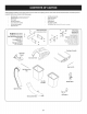
Beforebeginninginstallation,removeall partsfromthe cartonto makesureeverythingispresent.Cartoncontentsarelistedandshownbelow.Twohardwarepacksare includedinthiskit andaredetailedon the followingpage.
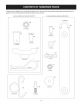
Thisgrasscollectorkit isshippedwith two CustomerReference Numbersenclosed.Pleasecheckyourcustomerreferencenumbersagainstthe illustrationsbelow.The quantitiesforeachitem islistedinparenthesiswhilethe partnumberis listedneareachitem.
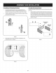
Assemblingthe MountingHardware AssembleMounting 8rackets 1. Toassemblethe baggermountingassembly,locatethe hitchbracketkit andfollow thesesteps: 2. If notalreadyinstalledbythefactory,installa shoulderboltfrom your hardwarepackontoeachbracket,securing themwith flangelocknutsalso includedinthe hardwarepackincludedwiththesebrackets.Referto Figure1. I. If alreadyinstalledinthe brackets,removethe clevispinsandclips,retainfor laterinstuctions.Referto Figure1.
2. Note:Thisuniversalmountingbracketassemblyisdesignedto workwith otheravailableattachments,suchasaweight kit usedinconjunctionwith the snowbladeor snowthrowerattachment.Utilizethe contactinformation MountAssemblyon Tractor onthe front or backcoverof thismanual,or contactthe storeinwhichyou purchased thisequipmentto find out moreaboutavailableattachmentsfor yourspecifictractor. 1.
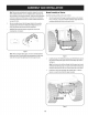
4, Tightenall of the hardwaresecuringthe hitchsupportat thistime. 5. Installthe uprightsupportbracketontothe mountingassemblyon the tractorbyhookingit overthe crossmountingbracketandaligningwith the right-sidemountingholeasshowninFigure7. Installthe hangerassemblyontothe uprightsupportbracketusingthe 5/16" carriagebolt packedlooselywith the uprightmountingbracket.Simply discardthe flangenut packedwith thecarriagebolt, andreplaceitwith the wing knob(720-04122)packedin hardwarepack689-00319.SeeFigure9.
Slidethe hingepin intothe holelocatedonthe mountingtab,asinFigure 12. Usethe cut-outwindow(Seeinsetin Figure12)to lineup the hingepin on the othersideandpushpinall the wayinuntil it reachesthe end-stop.At this pointthe pin clipsinto placeandissecuredbyatab inthe baggercover. SeeFigure13. AssemblingRemainingBaggerComponents Nowthat the mountingbracketsareassembledandareinplaceonthe tractor, followthesestepsto assemblethe remainingbaggercomponents. 1.
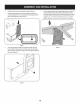
5. OpenHoodbypushingin onthe rear,right-sidetab with yourrighthand,as seenin 1of Figure14,andliftingthe coverwith yourleft handinthecenterrear ofthe baggercover,2. Installingthe DeckChute Note:Determineif yourdeckisa newermodel,or anoldermodel.Referto the upperinsetof Figure17.Ifyourdeckhasamountingstudpresent,then youhavea newerdeckmodelandyouwouldfollowthe instructionsbelow. Ifno studispresent,referto the instructions titled OnTractorsWith Older DeckConfigurations laterin thissection.
On Tractors with Older OeckConfigurations: 1. Installthe rubberchutestrap,from hardwarepack689-00313,ontothe chuteelbow usingthe clevispin(711-05063), washer(736-0204) andBow-tie cotterpin(714-04040) fromhardwarepack689-00313. SeeFigure18.Secure the endofthestraputilizingthe holefurthestfromthe end,insertthetorsionspring hook(732-04510A) intotheotherend. Note:Ondeckswithfrontdeckwheels,thebootmountrodmustberemoved in ordertoinstallthisdischarge chuteelbowontothetractor.SeeFigure18.
With the abilitynowto wigglethe dischargechutetubebackandforth,slide it overthe chuteelbowmountedonthe cuttingdeck,asshownin Figure24. Installingthe UpperChuteTube Peelthe backingoff ofthe self-adhesive foamstrip(721-04388)that has beenincludedwithin yourCartonof Contents.Applyit to the upperchute, flushagainstthe flangeasshownin Figure22. Figure24 Continuetowork the dischargechutedownoverthe chuteelbowuntil the grooveon thedischargechutealignswith the upperchutesupport,asseen inthe insetof Figure25.
Removethe grassbagsbylifting themup (1 inFigure28)andawayfromthe bagsupportassembly(2). Bagger Operation NOTE:Whenbothgrassbagsarefull, placethe tractoronafirm, levelsurface, disengagethe PTO(BladeEngage), turn thetractorengineoffandsetthe parking brake. 1, Fliptheseatup. 2. Opengrasscatchercoverbypushingin onthe rear,right-sidetab with your right-hand,asseenin 1of Figure27,andlifting with yourleft-handinthe rearcenter,2. Figure28 Figure 27 15 4. Emptythe grassclippingsat aproperdisposalsite.
LT_eriesMountKit i 34\ _1 I_ 2O _27 23 J 29 12 10 16
CRAFTSMAN TWOBINBAGGER Model No.247.240192 Topurchasereplacement parts, call 1-800-469-4663 I Ref, I Description Part Number 1. 689-00101 Mounting Bracket Kit (Incl. ref. 16, 17,18) 2. 710-3008 Hex Head Screw, 5/16-18 x .75" 3. 711-0309A Clevis Pin, .62" Dia. 4. 711-05049 Attachment Pin, 1/4 x 0.66 Lg. 5. 711-05063 Clevis Pin, 5/16 x .75 Lg. 6. 712-04063 Flange Lock Nut, 5/16-18 7. 712-3027 Flange Lock Nut, 1/4-20 8. 714-0117 Internal Cotter Pin, .148 x 3.00 9.
Sinstrucciones De Seguridad ............................................... 19-21 Contenido de la Caja ............................................................. 22-23 Montaje e Instalaci6n ........................................................... 24-30 Operaci6n ................................................................................... 31 Lista de piezas ......................................................................
Esta rnAquinarue construidapara seroperadade acuerdocon las reglasde seguridadcontenidasen este manual.AI igualque concualquiertipo de equipo rnotorizado,un descuidoo error por partedel operadorpuedeproducirlesionesgraves.Esta rnAquina es capazde arnputarrnanosy piesy de arrojarobjetoscon gran fuerza.Deno respetarlas instruccionesde seguridadsiguientesse puedenproducirlesionesgraveso la rnuerte.
4. Siga las recomendaciones del fabricante sobre pesos y contrapesos de las ruedas, para mejorar la estabilidad. 5. Haga que todos los movimientos en las pendientes sean lentos y graduales. No cambie repentinamente la velocidad ni la direcci6n. Un frenado o cambio de velocidad repentinos pueden causar que el frente de la m_quina se levante y d6 una voltereta hacia atr_s, Io que podria causar lesiones graves. 6. Servid0 general Evite arrancar o detenerse en una pendiente.
10° Pendiente "" 10 ° Pendiente (ACEPTAR) (DEiVIASlADO Figura1 - - " "" ESCARPADO) Figura2 0oI[nea - _ .-...diSC°ntinua US0 DEESTEPENDIENTE DECALIBREPARADETERiVIINAR SI UNAPENDiENTE ESDEIV1ASiADO ESCARPADO PARAUNAOPERACi(_N SEGURA! Paracomprobarla pendiente,hagaIosiguiente: 1. Borrarestap_.ginay doble a Io largo de la lineadiscontinua. 2. Localizarun objetoverticalsobreo detrJ.sde la pendiente(un poste,un edificio,unavalla, un _.rbol,etc.) 3.
Antesde comenzarlainstalad6n,retiretodaslaspiezasdelacajaparaasegurarse dequetienetodo.Elcontenidodelacajasemuestraacontinuad6n.Estekit incluyedos paquetesde herrajesquesedetallanenlap_iginasiguiente.
Estekit decolectorde hierbavienecondosnt_meros de referendadediente adjunto.Porfavorrevisesusnt_meros de referendadeclientecontralassiguientes Hustradones. Lascantidadesparacadaartkulo apareceentrepar_ntesismientrasqueelnumerode piezacotizacercadecadaelemento. Customer Reference Number 689-00319 Customer Reference Number 689-00313 723-04008A (1) (4) 712-04063 I I (1) (1) 711-05063 4) © 710-3008 711-0309A 736-0204 .
Ensamblarel Hardwarede montaje Armadode iasm nsuias de rnontaje 1. Instaleunpernoconreborde delpaquete deelementos enc_dam(_nsula, ajust_ndolos conlastuercas deseguridad conbridaquetambi(_n se encuentran enelpaquete. Consulte laFigure 1. Paraarmarlaunidadde montajedelaembolsadora, Iocaliceelkit de lam_nsulade enganchey sigaestospasos: 2. Instaleunpasadores dehorquilladelpaquete deelementos enc_da m_nsula, seguro conlastrinquetes conbridaquetambi_nseencuentran en elpaquete. Consulte la Figure 1. 1.
Montaje en el Tractor 3. Instalelosdospernosde horquillaconclipsdehorquillaconservados antes, comosemuestraen lafigura6, paraasegurarlapartesuperiordelaunidad de apoyodelenganche. 4. Aprietetodaslaspiezasquesujetanelsoportede enganche en este momento. Instaleel montajeeneltractorcomosigue: I. Coloquelosextremosenganchados delmontajedelrecogedorsobrelos pernosdehombro,comoen laFigure5,eneltractory alineeelorificio de soportedeengancheenel montajeconelagujerodeenganchedeltractor.
Instale alensamble delasuspensibn enelsoporte vertical utilizando el perno decarruaje de5/16"embalado sinapretar con elsoporte demontaje enposici6n vertical. Simplemente Deseche latuerca debrida embalada con elperno decarruaje yreemplazarlo con laperilla (720-04122) induida enel paquete dehardware 689-00319. Vea laFigure 9. Instalelacubiertade recogedor de hierbaenelconjuntodesoportedela bolsa,comoseveen laFigure11.
f "_ k,, _, 6. Instale ambas bolsas dehierbaenelconjunto desoporte debolsalnsertando el bordedelantero enprimera (1),comoseveenla Figure 15,y bajarel borde posterior (2)hastaqueencaje enlaAsamblea. Figure 13 5. Abraelcap6empujando lapestaffa trasera, ladoderecho conlamanoderecha, comoseveenla1delaFigure 14,y levantar latapaconlamano[zqulerda enla parteposterior decentrodelatapadelcontenedor, 2.
Instalaci6ndei conductode cubierta Enlos tractoresconmayoresconfiguradonesde cubierta: 1. Conconductodedescargadeltractorlevantadoy abierta(I), instaleel cododeconductocolocandolabarrademontajedelcododeconductoenel orifido correspondiente enelsoportedelaruedade cubiertao lengiJetade montajedelconducto(2),comoseveenla Figure16. Nora:Determinesisucubiertaesun modelonuevo,o un modeloantiguo. Consulteelrecuadrosuperiorde laFigure17.
0 Instalad6ndel tubo de conductosuperior Desprenda elrespaidode latira deespumaautoadhesiva(721-04388) que ha sidoincluida dentrodesucart6nde contenido.Aplicaa latolvasuperior, al rascontraelrebordecomosemuestraenlaFigure22. Figure20 Nora:Encubiertassinruedasdecubierta,engancharlacorreaderetenci6n enelorificiocorrespondiente en lapestaffaenla partefrontalde la plataformadecorte.Veala Figure21.
3. With theability now towiggle thedischarge chute tube back and forth, slide itover thechute elbow mounted onthecutting deck, asshown inFigure 24. Figure24 4. Continueto workthe dischargechutedown overthe chuteelbowuntil the grooveonthe dischargechutealignswith the upperchutesupport,asseen inthe insetof Figure25.
Fundonamiento de ia embolsadora NOTA:Cuandolosdoscubosparac#spedest#nIlenos,coloqueeltractor sobreunasuperfidefirmey nivelada,desenganche latomade fuerza(PTO), apagueel motordeltractory coloqueelfrenodeestadonamiento. 1. Eliminarloscubosde lahierbaporlevantarlashasta(1enla Figure2)y fuera de laasambleadeapoyobin(2). Volt_eelasientohadaarriba. Abralacubiertade c#spedempujandoenlapartetrasera,ladoderechodela fichaconsumanoderecha,comoseveen laFigure1.
This page intentionally left blank. Use this page to make any notes regarding 32 your bagger.