perator's I:RnFrSMRN° TWO BiN BAGGER Model No. 247.240193 • Espanol, p. 18 iMPORTANT: For answers to your questions this product, call: Read and follow all Safety Rules and instructions before operating about 1-800=659=5917 this equipment. Craftsman Tractor Help Line 7 am = 7 pm CT, Mort. =Sun. Sears Brands Management Visit Corporation, our website: Hoffman www.craftsman.com Estates, IL 60179 U.S.A. FormNo.
Safe Operation Practices .......................................................... 3-4 Slope Guide ...................................................................................... 5 Contents of Carton & Hardware Packs ................................ 6-7 Assembly and Installation ..................................................... 8-14 Operation ........................................................................................ 15 Parts List ....................................................
This symbol points outimportantsafety instructionswhich,if not followed, could endangerthe personalsafetyand/orproperty of yourselfandothers. Readandfollow all instructionsin this manual beforeattempting to operate this machine.Failureto complywith these instructionsmay resultin personalinjury.
Keep allmovement ontheslopes slow and gradual. Donotmake sudden changes inspeed ordirection. Rapid engagement orbraking could cause thefront ofthemachine toliftand rapidly flipover backwards which could cause serious injury. GENERAL SERVICE Beforecleaning,repairing, or inspecting, makecertainthe blade(s)andall movingpartshavestopped.Disconnect the sparkplugwire andground againstthe engineto preventunintendedstarting. Avoidstartingor stoppingona slope.
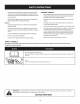
10° Slope 10° Slope (OK) (TOO STEEP) Figure 1 Figure2 10odashedline USETHiSSLOPEGAUGETO DETERMINE iF A SLOPEiS TOOSTEEPFORSAFEOPERATION! Tocheckthe slope, proceedas follows: 1. Removethis pageandfold along the dashedline. 2. Locatea vertical object on or behindthe slope(e.g. a pole,building,fence, tree, etc.) 3. Align either sideof the slopegaugewith the object (SeeFigure1 and Figure2 ). 4. Adjust gaugeup or down until the left cornertouchesthe slope(See Figure1 and Figure2). 5.
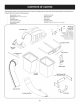
Beforebeginninginstallation,removeall partsfromthe cartonto makesureeverythingis present.Cartoncontentsarelistedandshownbelow.Twohardwarepacksare includedinthiskit andaredetailedon the followingpage. HitchBracket Kit(3brackets) MountingBracket Kit(2brackets & hardware) HitchSupport Discharge ChuteElbow Grass Catcher Cover Assembly TwoGrass BagAssemblies UpperChuteTube Self-Adhesive FoamStrip UpperChute Support HingeCover Pin UprightSupport BagSupport Assembly TwoHardware Packs(Detailed & Pictured _"_ \ .
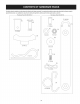
Estekit dec#spedsesuministracondosnumerosde referendasdeclientesencerrados. 5erecomiendaconsuitarlosnumerosdereferenciade losclientescontralas siguientesilustraciones.Lascantidadesdecadaartkulo seindicaentrepar#ntesis, mientrasqueel ntimeroaparecejuntoacadaitem. Hardware Pack for 689-00312 Hardware Pack 689-00313 I I (1) 723-04008/__. (1) (1) ) © 711-05063 (1) (1) 710-0276 711-0309A 736-0204 __ .
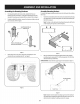
Assemblingthe Mounting Hardware AssembleMountingBrackets 1. Toassemblethe baggermountingassembly, locatethe hitchbracketkit andfollow thesesteps: 2. If notalreadyinstalled bythefactory,installa shoulderboltfrom your hardwarepackontoeachbracket,securing themwith flangelocknutsalso includedinthe hardwarepackincludedwiththesebrackets.Referto Figure1. 1. If alreadyinstalledinthe brackets,removethe clevispinsandclips,retainfor laterinstructions. Referto Figure1.
Installthe uprightsupportbracketontothe mountingassemblyonthe tractorbyhookingit overthe crossmountingbracketandaligningit with the mountingholeindicatingthe decksizeyourmachineisequippedwith, asshownin Figure7. MountAssemblyon Tractor Installthe mountingassemblyon the tractorasfollows: 1. Placethe hookedendsofthe baggermountingassemblyoverthe shoulder boltsonthe mountingbrackets previouslyinstalled onthetractorin Figure1. 2.
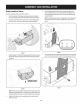
Installthe hangerassemblyontothe uprightsupportbracketusinga carriagebolt (710-0276) andwingknob(720-04122)from hardwarepack 689-00312.SeeFigure9. Installthe grasscatchercoverontothe bagsupportassembly, asseenin Figure11.Thegrasscatchercovergoesinsideof the two mountingtabson the bagsupportassembly. Figure 11 Slidethe hingepin intothe hole locatedonthe mountingtab,asin Figure 12.
f "_ 7. Installbothgrassbagsontothe bagsupportassemblybyinsertingthe front edgein first (1),asseeninFigure15,andsettingthe backedgedown(2) until it fits into the assembly. Figure13 5. Flipseatforward. 6. OpenHoodbypushingin onthe rear,right-sidetab with yourrighthand,as seenin1ofFigure14,andlifting thecoverwith yourleft handinthe centerrear ofthe baggercover,2.
Installingthe DeckChute OnTractorswith Older DeckConfigurations Note:Determineif yourdeckisa newermodel,or an oldermodel.Referto the upperinsetof Figure17.Ifyourdeckhasa mountingstudpresent,then youhaveanewerdeckmodelandyouwouldfollowthe instructionsbelow. If nostud ispresent,referto the instructionstitled OnTractorsWith Older DeckConfigurationslaterinthissection.
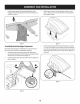
0 Installingthe UpperChuteTube Peelthe backingoff of the self-adhesive foamstrip (721-04388) that has beenincludedwithinyourContentsof Carton.Applyit to the upperchute, flushagainstthe flangeasshowninFigure22. Figure20 Note:Ondeckswithoutdeckwheels,hookthe retainerstrapintothe hole providedinthe flangeonthe front-sideof the cuttingdeck.SeeFigure21. / Figure22 With the grasscatchercoveropen,installthe upperdischargechutethrough the dischargechuteopening,asseenin Figure23.
3. Withthe ability nowto wigglethe dischargechutetubebackandforth,slide it overthechuteelbow mountedon the cuttingdeck,asshownin Figure24. Figure24 4. Continueto workthe dischargechutedown overthe chuteelbowuntil the grooveonthe dischargechutealignswith the upperchutesupport,asseen inthe insetof Figure25. Figure25 5. Closethegrasscatchercover.
BaggerOperation 4. NOTE: Whenbothgrassbagsarefull, placethe tractoronafirm, levelsurface, disengagethe PTO(BladeEngage), turnthe tractorengineoffandsetthe parking brake. Emptythe grassclippingsat aproperdisposalsite.Graspthe handleat the bottomof the bagwith onehand,andwiththe otherhandsteadythe bag, andemptythe contents. 5. Replace grassbags,closelid,flip downseat,restartyourtractorandresume cuttingyourgrass. 6. Retightenall wingknobsperiodicallythroughoutthe season. 1. Fliptheseatforward. 2.
2O 22 28 25 j29 19 j 16
CRAFTSMAN TWOBINBAGGER Model No.247.240193 Topurchase replacement parts,call1-800-469-4663 ! Ref, I Description Part Number 1. 689-00304 Mounting 2. 710-0276 Carriage 3. 711-0309A Clevis Pin, .62" Dia. 4. 711-05049 Attachment 5. 711-05063 Clevis Pin, 5/16 x .75 Lg. 6. 738-04267 Shoulder 7. 912-3027 Flange 8. 714-0117 Internal Cotter Pin, .148 x 3.00 9. 714-04040 Bow-Tie Cotter Pin, 72 10. 723-04008A Chute 11. 731-09173 Bagger 12. 720-04122 Wing Knob, 5/16-18 13.
Sinstrucciones De Seguridad ............................................... 19-21 Contenido de la Caja ............................................................. 22-23 Montaje e Instalaci6n ........................................................... 24-30 Operaci6n ................................................................................... 31 Lista de piezas ......................................................................
Esta rn&quinarue construidapara seroperadade acuerdocon las reglasde seguridadcontenidasen este manual.AI igualque concualquiertipo de equipo rnotorizado,un descuidoo error por partedel operadorpuedeproducirlesionesgraves.Esta rn&quina es capazde arnputarrnanosy piesy de arrojarobjetoscon gran fuerza.Deno respetarlas instruccionesde seguridadsiguientesse puedenproducirlesionesgraveso la rnuerte.
4. Siga las recomendaciones del fabricante contrapesos de las ruedas, para mejorar sobre pesos y la estabilidad. 5. Haga que todos los movimientos en las pendientes sean lentos y graduales. No cambie repentinamente la velocidad ni la direcci6n. Un frenado o cambio de velocidad repentinos pueden causar que el frente de la m_iquina se levante y d_ una voltereta hacia atr_is, Io que podria causar lesiones graves. Sewido general I. 6. Evite arrancar o detenerse en una pendiente.
10° Pendiente "" 10 ° Pendiente (ACEPTAR) (DEiVIASlADO Figura1 - - " "" ESCARPADO) Figura2 0oI[nea - _ .-...diSC°ntinua US0 DEESTEPENDIENTE DECALIBREPARADETERiVIINAR SI UNAPENDiENTE ESDEIV1ASiADO ESCARPADO PARAUNAOPERACi(_N SEGURA! Paracomprobarla pendiente,hagaIosiguiente: 1. Borrarestap_.ginay doble a Io largo de la lineadiscontinua. 2. Localizarun objetoverticalsobreo detrJ.sde la pendiente(un poste,un edificio,unavalla, un _.rbol,etc.) 3.
Antesde comenzarlainstalad6n,quitetodaslaspiezasdelacajaparaasegurarse dequetodoest_presente.Contenidodelacajaseenumerany semuestraacontinuad6n. Dospaquetesde hardwareseincluyenenestekit y sedetallanen lap_ginasiguiente.
Este kitdecolector dehierba viene con dos nt_meros dereferenda dediente adjunto. Por favor revise sus nt_meros dereferenda decliente contra lassiguientes Hustradones. Las cantMades para cada artkulo aparece entre par_ntesis mientras que elntimero depieza cotiza cerca decada elemento. Hardware Pack for689-00312 Hardware Pack 689-00313 _.
Ensamblarel Hardware de montaje Armadode iasm nsuias de montaje 1. Instale unpernoconreborde delpaquete deelementos enc_dam6nsula, ajust_ndolos conlastuercas deseguridad conbridaquetambi6n se encuentran enelpaquete. Consulte laFigure 28. Paraarmarlaunidadde montajedelaembolsadora, Iocaliceelkit de lam_nsulade enganchey sigaestospasos: 2. Instale unpasadores dehorquilladelpaquete deelementos enc_da m6nsula, seguro conlastrinquetes conbridaquetambi_nseencuentran en elpaquete. Consulte la Figure 28. 1.
Montaje en el Tractor Instaleel montajeeneltractorcomosigue: 1. 2. 3. Coloquelosextremosen formadeganchodelaasambleaembolsadora de montajesobrelostornillosde ajustedelossoportesdemontajepreviamente instalados eneltractoren Figure32. Instalelosdospasadores dehorquilla(711-0332) y seguroa lossoportes demontajecondospasadores clic(914-0145) queseincluyen conelkit de soportede montaje.
Instaleelconjuntodelganchoenelsoportede soporteverticalconun perno decarro(710-0276)y elpomodemariposa(720a04.122)dehardware paquete689-00312.verFigure36. Instalelacubiertade recogedor de hierbaenelconjuntodesoportedela bolsa,comoseveen laFigure38. Lacubiertadelcolectordehierbavadentro de lasdoslengiJetas demontajeenelconjuntodesoportedelabolsa. Figure36 Figure38 Montajede ioscomponentes restantesdel recogedor 4.
f "_ 7. Instaleambasbolsasdehierbaen elconjuntodesoportede bolsainsertando el bordedelanteroen primera(1),comoseveenla Figure42,y bajarelborde posterior(2)hastaqueencajeen laAsamblea. Figure40 Muevaelaslentohadaadelante. 6, Abraelcap6empujandolapestaffatrasera,ladoderechoconlamanoderecha, comoseveenla(1)delaFigure41,y levantarlatapaconlamanoizquierdaen laparteposteriordecentrodelatapadelcontenedor, (2).
Instalaci6ndei conductode cubierta 8. Enlostractoresconmayoresconfiguradones decubierta Hera:Determinesisucubiertaesun modelonuevo,o un modeloantiguo. Consulteelrecuadrosuperiorde laFigure44. Sisucubiertatieneun pernode montajepresente,tendr_un nuevomodelode cubiertay quedeberiaseguir lassiguientesinstrucciones. Sino poste,consultelasinstrucciones tituladas entractores conmayorescubierta configuradonesm_sadelanteen estasecci6n.
0 Instalad6ndei tubo de conductosuperior Desprenda elrespaldode latira deespumaautoadhesiva(721-04388) que ha sidoincluida dentrodesucart6nde contenido.Aplicaa latolvasuperior, al rascontraelrebordecomosemuestraen laFigure49. Figure47 Nora:Encubiertassinruedasdecubierta,engancharlacorreaderetenci6n enelorificiocorrespondiente en lapestaffaenla partefrontalde la plataformadecorte.Veala Figure48.
3. With theability now towiggle thedischarge chute tube back and forth, slide itover thechute elbow mounted onthecutting deck, asshown inFigure 51. Figure51 4, Continueto workthe dischargechutedown overthe chuteelbowuntil the grooveonthe dischargechutealignswith the upperchutesupport,asseen inthe insetof Figure52.
Fundonamiento de ia embolsadora Eliminarloscubosde laHerbaporlevantarlashasta(1enla Figure54)y fuerade laasambleadeapoyobin(2). NOTA: Cuandolosdoscubosparac_spedest_nIlenos,coloqueeltractor sobreunasuperfidefirmey nivelada,desenganche latomade fuerza(PTO), apagueel motordeltractory coloqueelfrenodeestadonamiento. 1. Volt_eelasientohadaarriba.
This page intentionally left blank. Use this page to make any notes regarding 32 your bagger.