Safe Operation Practices • Set-Up • Operation • Maintenance • Service • Troubleshooting • Warranty Operator’s Manual Single-Stage Snow Thrower — Model 2M1 WARNING READ AND FOLLOW ALL SAFETY RULES AND INSTRUCTIONS IN THIS MANUAL BEFORE ATTEMPTING TO OPERATE THIS MACHINE. FAILURE TO COMPLY WITH THESE INSTRUCTIONS MAY RESULT IN PERSONAL INJURY. MTD LLC, P.O. BOX 361131 CLEVELAND, OHIO 44136-0019 Printed In USA Form No.
1 To The Owner Thank You Thank you for purchasing a Snow Thrower manufactured by MTD LLC. It was carefully engineered to provide excellent performance when properly operated and maintained. Please read this entire manual prior to operating the equipment. It instructs you how to safely and easily set up, operate and maintain your machine. Please be sure that you, and any other persons who will operate the machine, carefully follow the recommended safety practices at all times.
Important Safe Operation Practices 2 WARNING! This symbol points out important safety instructions which, if not followed, could endanger the personal safety and/or property of yourself and others. Read and follow all instructions in this manual before attempting to operate this machine. Failure to comply with these instructions may result in personal injury. When you see this symbol.
Safe Handling of Gasoline 5. To avoid personal injury or property damage use extreme care in handling gasoline. Gasoline is extremely flammable and the vapors are explosive. Serious personal injury can occur when gasoline is spilled on yourself or your clothes which can ignite. Wash your skin and change clothes immediately. Never run an engine indoors or in a poorly ventilated area. Engine exhaust contains carbon monoxide, an odorless and deadly gas. 6.
Maintenance & Storage Do not modify engine 1. Never tamper with safety devices. Check their proper operation regularly. Refer to the maintenance and adjustment sections of this manual. 2. Before cleaning, repairing, or inspecting machine disengage all control levers and stop the engine. Wait until the auger/impeller come to a complete stop. Disconnect the spark plug wire and ground against the engine to prevent unintended starting. To avoid serious injury or death, do not modify engine in any way.
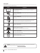
Safety Symbols This page depicts and describes safety symbols that may appear on this product. Read, understand, and follow all instructions on the machine before attempting to assemble and operate. Symbol Description READ THE OPERATOR’S MANUAL(S) Read, understand, and follow all instructions in the manual(s) before attempting to assemble and operate WARNING— ROTATING BLADES Keep hands out of inlet and discharge openings while machine is running.
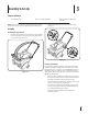
3 Assembly & Set-Up Contents of Carton • Two Ignition Keys • One 20 oz. Bottle 5W-30 Oil NOTE: All references to the left or right side of the snow thrower are from the operator’s position. Any exceptions will be noted. 2. • One Snow Thrower Operator’s Manual Tighten the wing knobs to secure the handle in place. See Fig. 3-2. Assembly Positioning the Upper Handle 1. Pivot the upper handle into the operating position making sure not to pinch the cable in the process, as illustrated in Fig.
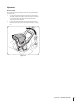
2. Adding Fuel WARNING! Use extreme care when handling gasoline. Gasoline is extremely flammable and the vapors are explosive. Never fuel the machine indoors or while the engine is hot or running. Extinguish cigarettes, cigars, pipes and other sources of ignition. Slowly add oil until the oil level registers between high (H) and low (L), Fig. 3-4. Refer to the Engine Maintenance section for the correct oil viscosity and engine oil capacity.
Adjustments Chute Assembly The pitch of the chute assembly controls the angle at which the snow is thrown. 1. Loosen the wing knob found on the left side of the chute assembly and pivot the upper chute upward or downward to the desired pitch. Retighten the wing knob before operating the snow thrower. 2. Position the chute assembly opening by using the chute handle to throw the snow in the desired direction. See Fig. 3-5.
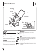
4 Controls and Features Recoil Starter Handle Ignition Key Auger Control Primer Gas Cap Control Handle Chute Assembly Exhaust Spark Plug/ Spark Plug Boot Choke Lever Shave Plate Auger Choke Lever Oil Fill Cap w/ Dipstick Oil Drain Recoil Starter Handle Figure 4-1 Recoil Starter The starter handle is used to manually start the engine. Gasoline Cap Activating the choke control closes the choke plate on carburetor and aids in starting engine.
Chute Assembly Rotate the discharge chute to the left or right using the chute handle. The pitch of the discharge chute controls the angle at which the snow is thrown. Loosen the wing knob on the side of the discharge chute before pivoting the discharge chute upward or downward. Retighten the knob once the desired position has been achieved. Shave Plate The shave plate maintains contact with the pavement as the snow thrower is propelled, allowing snow close to the pavement’s surface to be discharged.
5 Operation Before Starting 9. WARNING! Read, understand and follow all the instructions and warnings on the machine and in this manual before operating. 1. The spark plug wire was disconnected for safety. Attach the spark plug wire to the spark plug before starting. Starting the Engine As the engine warms up and begins to operate evenly, slide the choke lever slowly to the 1⁄2 choke position. When the engine begins to run smoothly, move the choke to the OFF position.
Notes Section 5 — Operation 13
6 Maintenance & Adjustments Adjustments Control Cable WARNING! Before Servicing, repairing or inspecting the snow thrower, disengage the auger control. Stop the engine and remove the key to prevent unintended starting. Shave Plate 1. To check the adjustment of the shave plate, place the machine on a level surface. The wheels, shave plate and augers should all contact the level surface. Note that if the shave plate is adjusted too high, snow may blow under the housing.
7 Engine Maintenance WARNING! To prevent accidental start-up, shut off the engine and remove the ignition key before performing any type of engine maintenance. Periodic inspection and adjustment of the engine is essential if high level performance is to be maintained. Regular maintenance will also ensure a long service life. The required service intervals and the type of maintenance to be performed are described in the table below. Follow the hourly or calendar intervals, whichever occur first.
Spark Plug Oil Recommendations When adding oil to the engine, refer to the viscosity chart below (Fig. 7-2). Engine oil capacity is 600 ml (approx. 20 oz.). Do not over-fill. Use a 4-stroke, or an equivalent high detergent, premium quality motor oil certified to meet or exceed U.S. automobile manufacturer’s requirements for service classification SG, SF. Motor oils classified SG, SF will show this designation on the container. WARNING! DO NOT check for a spark with the spark plug removed.
3. Measure the plug gap with a feeler gauge. Correct as necessary by bending the side electrode, Fig. 7-4. The gap should be set to .02-.03 inches (0.60-0.80 mm). Off-Season Storage Electrode 1. Remove all fuel from the tank by running the engine until it stops. 2. Change the engine oil. 3. Remove the spark plug and pour approximately 1 oz. (30 ml) of clean engine oil into the cylinder. Pull the recoil starter several times to distribute the oil, and reinstall the spark plug. 4.
8 Service Replacing Belt 1. To replace the belt follow these instructions and refer to Fig. 7-2: Remove the belt cover by removing the five hex screws that secure it to the frame. See Fig. 7-1. 1 3 Auger Pulley Idler Pulley Belt Keeper Engine Pulley Hex Screws 2 4 Figure 7-2 2. 1. Push down on the idler pulley. Figure 7-1 2. Remove the belt by grasping it from the bottom of the auger pulley and pulling outward. Position the belt on top of the auger pulley and under the belt keeper. 3.
Replacing Auger Paddles The snow thrower auger’s rubber paddles are subject to wear and should be replaced if any signs of excessive wear are present. Cauton: Do NOT allow the auger’s rubber paddles to wear to the point where portions of the metal auger itself can come in contact with the pavement. Doing so can result in serious damage to your snow thrower. To change the rubber paddles, proceed as follows: 1.
9 Troubleshooting Problem Engine Fails to start Engine runs erratic Cause Remedy 1. Fuel tank empty, or stale fuel. 1. Fill tank with clean fresh gasoline. 2. Blocked fuel line. 2. Clean fuel line. 3. Key not inserted all the way. 3. Insert key all the way. 4. Spark plug wire disconnected. 4. Connect wire to spark plug. 5. Faulty spark plug. 5. Clean spark plug, readjust gap, or replace. 6. Engine not primed. 6. Prime engine five to seven times. 7. Engine flooded from excessive priming. 7.
10 Replacement Parts Component Part Number and Description 731-1033 Shave Plate 754-0101A Belt V-Type 735-04032 735-04033 753-04472 Spiral Crescent Rubber Paddle Replacement Kit (includes 4 crescents, 2 paddles and hardware) 731-05632 Key 746-04237 Clutch Cable 951-10292 Spark Plug Phone (800) 800-7310 to order replacement parts or a complete Parts Manual (have your full model number and serial number ready). Parts Manual downloads are also available free of charge at www.mtdproducts.com.
MTD CONSUMER GROUP INC (MTD), the California Air Resources Board (CARB) and the United States Environment Protection Agency (U. S. EPA) Emission Control System Warranty Statement (Owner’s Defect Warranty Rights and Obligations) EMISSION CONTROL SYSTEM COVERAGE IS APPLICABLE TO CERTIFIED ENGINES PURCHASED IN CALIFORNIA IN 2005 AND THEREAFTER, WHICH ARE USED IN CALIFORNIA, AND TO CERTIFIED MODEL YEAR 2005 AND LATER ENGINES WHICH ARE PURCHASED AND USED ELSEWHERE IN THE UNITED STATES.
(4) Repair or replacement of any warranted part under the warranty provisions of this article must be performed at no charge to the owner at a warranty station. (5) Notwithstanding the provisions of Subsection (4) above, warranty services or repairs must be provided at all MTD distribution centers that are franchised to service the subject engines.
MANUFACTURER’S LIMITED WARRANTY FOR The limited warranty set forth below is given by MTD LLC with respect to new merchandise purchased and used in the United States and/or its territories and possessions, and by MTD Products Limited with respect to new merchandise purchased and used in Canada and/ or its territories and possessions (either entity respectively, “MTD”).
Medidas importantes de seguridad • Configuración • Funcionamiento • Mantenimiento • Servicio • Solución de problemas • Garantía Manual del Operador Máquina quitanieve de etapa única — Modelo 2M1 ADVERTENCIA LEA Y RESPETE TODAS LAS NORMAS DE SEGURIDAD E INSTRUCCIONES INCLUIDAS EN ESTE MANUAL ANTES DE PONER EN FUNCIONAMIENTO ESTA MÁQUINA. SI NO RESPETA ESTAS INSTRUCCIONES PUEDE PROVOCAR LESIONES PERSONALES. MTD LLC.
Al propietario 1 Gracias Gracias por comprar una máquina quitanieve fabricada por MTD LLC. La misma ha sido diseñada cuidadosamente para brindar excelente rendimiento si se la opera y mantiene correctamente. Por favor lea todo este manual antes de operar el equipo. Le indica cómo configurar, operar y mantener la máquina con seguridad y fácilmente.
2 Medidas importantes de seguridad ¡ADVERTENCIA! La presencia de este símbolo indica que se trata de instrucciones importantes de seguridad que se deben respetar para evitar poner en peligro su seguridad personal y/o material y la de otras personas. Lea y siga todas las instrucciones de este manual antes de poner en funcionamiento esta máquina. Si no respeta estas instrucciones puede provocar lesiones personales. Cuando vea este símbolo.
Manejo seguro de la gasolina Para evitar lesiones personales o daños materiales tenga mucho cuidado cuando trabaje con gasolina. La gasolina es sumamente inflamable y sus vapores pueden causar explosiones. Si se derrama gasolina encima o sobre la ropa se puede lesionar gravemente ya que se puede incendiar. Lávese la piel y cámbiese de ropa de inmediato. a. b. Utilice sólo los recipientes para gasolina autorizados. Apague todos los cigarrillos, cigarros, pipas y otras fuentes de combustión. c.
Mantenimiento y Almacenamiento No modifique el motor 1. Nunca altere los dispositivos de seguridad. Controle periódicamente que funcionen correctamente. Remítase a las secciones de mantenimiento y ajuste de este manual. 2. Antes de realizar la limpieza, reparar o revisar la máquina, desengrane todas las palancas de control y detenga el motor. Espere a que la barrena / impulsor se detenga por completo.
Símbolos de Seguridad Esta página describe los símbolos y figuras de seguridad internacionales que pueden aparecer en este producto. Lea el manual del operador para obtener la información terminada sobre seguridad, reunirse, operación y mantenimiento y reparación. Símbolo Descripción LEA EL MANUAL DEL OPERADOR (S) Lea, entienda, y siga todas las instrucciones en el manual (es) antes de intentar reunirse y funcionar.
Montaje y Configuración 3 Contenido de la caja • Dos llaves de encendido • Una botella de 20 oz. de aceite 5W-30 NOTA: Todas las referencias a los lados derecho o izquierdo de la máquina quitanieve se hacen observando la misma desde la posición del operador. En caso de que hubiese una excepción, se especificará claramente. 2. • Un Manual del Operador de la Máquina Quitanieve Ajuste las perillas de aletas para sujetar la manija en su lugar. Vea la Fig. 3-2.
2. Carga de combustible ¡ADVERTENCIA! Tenga mucho cuidado al trabajar con gasolina. La gasolina es sumamente inflamable y sus vapores pueden causar explosiones. Nunca agregue combustible a la máquina en interiores ni mientras el motor está caliente o en funcionamiento. Apague cigarrillos, cigarros, pipas y otras fuentes de combustión. Agregue aceite lentamente hasta que el registro marque entre nivel alto (H) y bajo (L), Figura 3-4.
Ajustes Montaje del canal La inclinación del montaje del canal controla el ángulo con el que se arroja la nieve. 1. Afloje la perilla de paletas que se encuentra del lado izquierdo del montaje del canal y gire el canal superior hacia arriba o hacia abajo hasta alcanzar la inclinación deseada. Vuelva a ajustar la perilla de paletas antes de poner la máquina quitanieve en funcionamiento. 2. Posicione la abertura del montaje del canal con la manija del canal para arrojar la nieve en la dirección deseada.
Controles y Características 4 Manija del arrancador de retroceso Llave de encendido Control de la barrena Cebador Tapa de combustible Manija de control Montaje del canal Escape Placa de raspado Palanca del cebador Tapón de llenado de aceite c/ varilla de medición del nivel de aceite Tubo de drenaje del aceite Barrena Palanca del cebador Bujía / Funda de la bujía Manija del arrancador de retroceso Figura 4-1 Arrancador de retroceso La manija del arrancador se utiliza para arrancar el motor manu
Montaje del canal Haga rotar el canal de descarga hacia la izquierda o derecha usando la manija del canal. La inclinación del canal de descarga controla el ángulo con el que se arroja la nieve. Afloje la perilla de aletas del costado del canal de descarga antes de girar el canal de descarga hacia arriba o hacia abajo. Vuelva a ajustar la perilla después de alcanzar la posición deseada.
Funcionamiento Antes de encender la máquina ¡ADVERTENCIA! Lea, comprenda y siga todas las instrucciones y advertencias que aparecen en la máquina y en este manual antes de operarla. 1. 5 8. Tire de la manija del arrancador rápidamente. No permita que la manija retroceda a su posición original. Permita que se enrolle lentamente mientras sujeta firmemente la manija del arrancador. 9.
Notas Sección 5— Funcionamiento 13
Mantenimiento y Ajustes Ajustes Cable de control ¡ADVERTENCIA! Antes de realizar tareas de mantenimiento, reparación o inspección en la máquina quitanieve, desengrane el control de la barrena. Apague el motor y retire la llave para evitar el encendido accidental del motor. Placa de raspado 1. 6 Para verificar el ajuste de la placa de raspado, ubique la unidad sobre una superficie nivelada. Las ruedas, la placa de raspado y las barrenas deben tocar la superficie nivelada.
Mantenimiento del motor 7 ¡ADVERTENCIA! Para evitar el arranque accidental, apague el motor y retire la llave de encendido antes de realizar cualquier tipo de mantenimiento del motor. Calendario de mantenimiento Tarea Primeras 5 horas. Cada uso o cada 5 horas. La inspección y los ajustes periódicos del motor son esenciales si se desea mantener un alto nivel de desempeño. El mantenimiento regular también garantizará una prolongada vida útil del motor.
Bujía de encendido Recomendaciones sobre el aceite Cuando le agregue aceite al motor, consulte la siguiente tabla de viscosidad (Fig. 7-2). La capacidad de aceite del motor es 600 ml (aprox. 20 onzas). No llene excesivamente. Use un aceite para motor de cuatro tiempos, o un aceite detergente de calidad premium equivalente con certificado que cubra o exceda las exigencias de los fabricantes de automóviles americanos respecto de la clasificación de servicio SG y SF.
1. Mida la separación de bujía con un calibrador. Realice los ajustes necesarios torciendo el electrodo lateral, Fig. 7-4. La separación de ajustarse en 0,02-0,03 pulgadas (0,60-0,80 mm). Almacenamiento fuera de temporada Los motores que se almacenan durante más de 30 días deben ser drenados de combustible para evitar que se deterioren y se forme goma en el sistema de combustible o en las piezas principales del carburador.
Servicio 8 Reemplazo de las correas 1. Para sacar la cubierta de la correa saque los cinco tornillos hexagonales y las arandelas que la sujetan al bastidor. Vea la Fig. 7-1. Para volver a colocar la correa siga estas instrucciones y consulte la Fig. 7-2: 1 3 Polea de la barrena Polea del motor Polea loca Tornillos de cabeza hexagonal 2 4 Figura 7-2 Figura 7-1 2. Retire la correa sujetándola por la base de la polea de la barrena y tire hacia afuera.
Reemplazo de las paletas de la barrena Las paletas de caucho de la barrena de la máquina quitanieve se desgastan y se las debe cambiar si se presentan signos de desgaste excesivo. Precaución: NO permita que las paletas de caucho de la barrena se desgasten hasta el punto en que partes de la barrena metálica misma toquen el pavimento. Si esto sucede la máquina quitanieve puede dañarse seriamente. Para cambiar las paletas de caucho proceda de la siguiente manera: 1.
Solución de Problemas Problema El motor no arranca 9 Causa 1. El depósito de combustible está vacío o el combustible se ha echado a perder. 2. La línea del combustible está bloqueada. 3. No se introdujo completamente la llave. 4. Se ha desconectado el cable de la bujía. 5. La bujía no funciona correctamente. 6. El motor no está cebado. 7. El motor está ahogado ya que ha sido cebado demasiado. Solución 1. Llene el depósito con gasolina limpia y nueva. 2. Limpie la línea del combustible. 3.
Notas 10 21
MTD CONSUMER GROUP, INC. (MTD), el Bordo de Recursos de Aire de California (CARB) y la Agencia de Protección Medioambiental de Estados Unidos (U. S.
reemplazada según la garantía se garantizará por el resto del período de garantía. (3) Cualquier pieza garantizada que esté programada para reemplazo según el mantenimiento requerido de conformidad con las instrucciones escritas de la Subsección (c) se garantiza por el período de tiempo anterior a la primera fecha de reemplazo programada para esa pieza. Si la pieza falla antes del primer reemplazo programado, la misma será reparada o reemplazada por MTD de acuerdo con la Subsección (4) a continuación.
GARANTÍA LIMITADA DEL FABRICANTE PARA La siguiente garantía limitada es otorgada por MTD LLC con respecto a nuevos productos adquiridos y utilizados en Estados Unidosy/o sus territorios y posesiones, y por MTD Products Limited con respecto a nuevos productos adquiridos y utilizados en Canadá y/o sus territorios y posesiones (cualquiera de las dos entidades, respectivamente, “MTD”).