v® m al @ Trimmer iMPORTANT: READ SAFETY RULES AND iNSTRUCTiONS PiN 769-01467 (10/04) PRINTED IN USA CAREFULLY
THANK YOU TABLE Thank you for buying this quaHity product. This modern outdoor power tooH wiHHprovide many hours of usefuH service. You wiHHfind it to be a great Habor-saving device. This operator's manuaH provides you with easy-tounderstand operating instructions. Read the whoHe manuaH and foHHowaHH the instructions to keep your new outdoor power tooH in top operating condition. OF CONTENTS Service Information ......................... Rules for Safe Operation Know Your Unit .......................
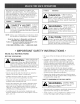
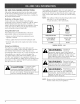
The purpose of safety symbols is to attract your attention to possible dangers, The safety symbols, and their explanations, deserve your careful attention and understanding. The safety warnings do not by themselves eliminate any danger, The instructions or warnings they give are not substitutes for proper accident prevention measures, SYMBOL SYMBOL DANGER: Failure to obey a safety warning will result in serious injury to yourself or to others.
• Alwaysstoptheengineandallowittocoolbeforefilling thefueltank.Neverremove thecapofthefueltank,or addfuei,whentheengineishot.Neveroperatetheunit withoutthefuelcapsecurely in place.Loosenthefuel tankcapslowlytorelieveanypressure inthetank. • Mixandaddfuelina clean,well-ventilated outdoorarea wheretherearenosparksor flames.Slowlyremove the fuelcaponlyafterstoppingengine.Donotsmokewhile fuelingor mixingfuel.Wipeupanyspilledfuelfromthe unitimmediately. Alwayswipeunitdrybeforeusing. Movetheunitatbast 30feet(9.
SAFETY AND _NTERNAT_ONAL SYMBOLS This operator's manual describes safety and international symbols and pictographs that may appear on this product. Read the operator's manual for complete safety, assembly, operating and maintenance and repair information. SYMBOL MEANING SYMBOL Indicates danger, warning, or , SAFETY ALERT SYMBOL caution. May be used in conjunction with other symbols or pictographs.
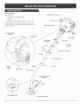
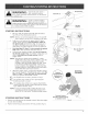
APPMCATmONS Blue EZ-Start As a trimmer: • Cutting • Decorative TM Lever grass and Hight weeds, trimming around trees, fences, etc, Other optional accessories may be used with the TB20CS, Refer to Operadng the EZ-Link .System for a Hist of add-ons, Starter Rope Gri f AirFHter/Muffler Cover Muffler BmueEZ=Start Lever Spark Plug / On/Off Stop Control Shaft Grip Throttle Controm Shoulder D=Hand_e ShaR Housing Engine Stand \ EZ-Link Muffler Cutting Attachment Shield / Line Cutting B
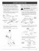
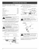
INSTALL AND ADJUST THE D-HANDLE 3. mNSTALL THE CUTTING ATTACHMENT SHIELD Use the following instructions if the cutting attachment shield on your unit is not installed. The squared bolt hole in the handle is to the right. 2. Insert the shoulder bolt into the squared hole in the handle and push through. On the left side of the handle, place the washer on the bolt, then screw the wing nut onto the bolt. Do not tighten until you make the handle adjustment. 3.
OraLAND FUEL MmXH_G H_STRUCTmONS ON and/or improperly mixed fuel are the main reasons for the unit not running properly. Be sure to use fresh, cban unleaded fuel. Follow the instructions carefully for the proper fue%il mixture. Definition of Bmended Fuels Today's fueis are often a bbnd of gasoiine and oxygenates such as ethanol, methanol, or MTBE (ether). AIcohol-bbnded fuel absorbs water. As littb as 1% water in the fue[ can make rue[ and oi[ separate, it forms acids when stored.
WARBLING: Operateth,s un,t only,na vvellventilated outdoor area,Carbon monoxide exhaustfumes can be lethal in a confinedarea, Stop/Off Start/On (O) ( I) WARNING: Avoid acddentd starting. Make sure you are in the starting position when pulling the starter rope (Fig. 8). To avoid serious injury, the operator and unit must be in a staMe position while starting. STARTING Throttle Control INSTRUCTIONS 1. Mix gas with oil. Fill fuel tank with fuel/oil mixture. See Oil and Fuel Mixing Instructions.
OPERATING THE EZ-UNK TM SYSTEM The EZ-LinW M system enabHes the use of these optionaH Add-Ons. Cultivator ................................ TBGC Edger ................................... Hedge Trimmer ........................... TBLE TBAH Straight Shaft Trimmer ...................... Turbo BHower ............................. TBSS TBTB PorteSaw ................................ Brushcutter with an electric Beforeyou begin usingany Attachment 1. Turn the knob counterclockwise 2.
HOLDmNG THE TRmMMER WARNmNG: AUways wear eye, hearing, foot and body protection to reduce the risk of injury when operating this unit, NOTE: Do not rest the Bump Head TM on the ground whiie the unit is running. Some iine breakage wiii occur from: • Entangiement with foreign matter • Normal line fatigue Before operating the unit, stand in the operating position (Fig.
MAmNTENANCE SCHEDULE Perform these required maintenance procedures at the frequency stated in the tame. These procedures shouHd also be a part of any seasonaHtune-up. NOTE: Some maintenance procedures may require speciaH tooHsor skills. If you are unsure about these procedures take your unit to any non-road engine repair estaMishment, individuaH or authorized service deaHer. WARNING: To prevent senous injury, never perform maintenance or repairs with unit running. AHways service and repair a cooH unit.
ForUsewithSingme LineONLY ForUsewithSplitLine TM or Singme Line 9. Insert the end of the line into the open hole in the inner reel and pull the line tight to make the loop as small as possible (Fig. 21). 10. Before winding, split the line back about 6 inches. 11. Wind the line in tight even layers in the direction indicated on the inner reel. NOTE: Failure to wind the line in the direction indicated wi[[ cause the cutting attachment to operate incorrectly. FWg.
mNSTALUNG A PREWOUND REEL 1. Hold the outer spool with one hand and unscrew the bump knob counterclockwise (Fig. 15). Inspect the boHt inside the bump knob to make sure it moves freeHy. RepHacethe bump knob if damaged. 2. Remove the oHdinner reeHfrom the outer spooH (Fig. 16). 3. Remove the spring from the oHdinner reeH (Fig. 16). 4. Mace the spring in the new inner reel NOTE: The spring must be assemMed on the inner reeH before reassemMing the cutting attachment. 5.
SPARK ARRESTOR MAINTENANCE 8. NOTE: The exhaust can onHyflow in one direction: AWAY from the engine. Pay chose attention when disassemMing the muffHer so you can put it back together correctHy. FaiHureto do so will damage the unit and may cause serious personaH injury. 9. Replace the two screws you removed in Step 2 and tighten them securely. Reinstall the air filter/muffler cover.
2. Release the throttb trigger and let the engine idle. If the engine stops, insert a small phillips or flat blade screwdriver into the hole in the air filter/muffler cover (Fig. 30). Turn the idle speed screw in, clockwise, 1/8 of a turn at a time (as needed) until the engine idles smoothly. NOTE: The cutting attachment should not rotate when the engine idles. 3.
CAUSE ACTION Empty fueHtank Fill fueHtankwithpropedy mixed fueH Primer buHbwasn't pressed enough Press primer bulb fully and slowly 10 times Engine is flooded Squeeze the trigger and pull the starter rope OHdor impropeHy mixed fueH Drain gas tank and add fresh fuel mixture FouHed spark pHug Replace or clean the spark plug Mugged spark arrestor Clean or replace spark arrestor BHueEZ-Start Heverwasn't flipped/set Move lever to the starting position The outside temperature is bellow 40 ° F Pu
EngineType.......................................................................................................................................... Air-Cooled, 2-Cycle Stroke.................................................................................................................................................... 1.25in.(31.75mm) Displacement ............................................................................................................................................. 1.9cu in.
California / EPA Emission Your Warranty ControJ Rights Warranty Statement and Obligations The California Air Resources Board, the Envkonmentd Protection Agency and MTD LLC (MTD) are pHeased to exphin the emission controH system warranty on your 2000 and Hatersmall off-road engine, New small off-road engines must be designed, buiHtand equipped to meet stringent anti-smog standards, MTD must warrant the emission controH system on your small off-road engine for the periods of time Histed bellow provided
MANUFACTURER'S LIMITED WARRANTY FOR: TRO BI£T The limited warranty set forth below is given by Troy-Bilt LLC with respect to new merchandise purchased and used in the United States, its possessions and territories. Troy-Bilt LLC warrants this product against defects in material and workmanship for a period of two (2) years commencing on the date of original purchase and will, at its option, repair or replace, free of charge, any part found to be defective in material or workmanship.