
Owner Manual

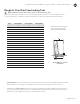

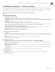
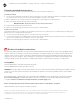
Table Of Contents

Installation and Operational Manual
°
Designer Collection
°
Acrylic Freestanding Tubs
7 / mtibaths.com
MTI does not warrant leaks associated with improper drain or valve installation and will not be responsible for any costs involved with removing or reinstalling
the tub. Failure to check floor for flat & level surface, or properly water test the tub & drain, which could will result in improper drainage of the bath, is the
reponsibility of the installer. If you need assistance, please call the MTI Service Department at 800-783-8827.
Plumbing Installation Instructions
Access panel comes standard on tub models with integral faucet deck and optonal virtual spout.
1. Use access panel behind the integral faucet deck to install valves in accordance with valve manufacturer’s installation instructions. If
your tub model does not have an access panel for valve installation, check your order details.
2. MTI recommends the use of braided stainless steel supply lines for best fit between the walls of the tub.
3. Mark on the faucet deck the planned location of each valve.
BEFORE DRILLING: Dry fit valve trim to ensure proper fit and clearance.
4. Acrylic tub may be drilled using carbide hole saw.
5. Water test for leaks all supply line and valve connections prior to final installation.
See Important Safety Information on page 1 of this manual and Electrical Specifications on the next page. Many options
may be combined on a 20 amp circuit, as long as total amps of combined options are considered. If your tub has more
than two power cords, the power cords will be gathered together with a hang tag indicating how many items must be
plugged in for proper operation. This circuit must be connected to a supply that is protected by a ground fault circuit
interrupter (GFCI). Such a GFCI should be provided by the installer, and accessible for testing on a routine basis.
Testing GFCI
Push the TEST button. The GFCI should interrupt power.
Push the RESET button. Power should be restored.
WARNING: If the GFCI fails to operate in this manner, there is a ground current flowing, indicating the possibility of electric
shock. Do not use this unit. Disconnect the unit and have the problem corrected by a qualified service representative
before using.
Every MTIair blower is supplied with a 29” grounded cord and NEMA plug to be plugged into a grounded receptacle*.
Do not remove this plug. If a wall mount switch is desired to control use of the unit, the switch should control the
receptacle. Under no circumstance should you alter the provided supply cord.
Before servicing unit, shut off all electrical outlets as more than one outlet may be energized.
*NOTE: Air blowers do not require a bonding conductor.
Electrical installation instructions
Deck Mounted Valves
Virtual Spout Connection
Optional Virtual Spout is factory installed in the tub wall and intended for use as a tub filler in lieu of a traditional faucet or filling spout.
Mixing valves are not supplied with the Virtual Spout.
1. Tee the the hot and cold supply lines before connecting to the stub out on the tub
2. Connect mixed supply line to the Wilkins dual check valve that is factory installed between the walls of the tub. If your tub model does
not have an access panel for valve installation, check your order details.
3. Water test for leaks all supply line and valve connections prior to final installation.