
FLETA PRO V2 Manual

FLETA PRO V2 ESC USER MANUAL
Thank you for purchase of Much-More Racing FLETA PRO V2 electronic speed controller.
New FLETA PRO V2 is specifically designed for 1/10 scale electric R/C racing.
No matter which class of competition you race in, the FLETA will help you achieve better results.
Before you start, please read through this instruction manual carefully.
It contains important safety information as well as setup tips from Much-More Racing website.
• NEW Position changeable switch & BEC wire
• NEW Direct motor cooling fan power
• NEW Reversible switch system [RSS]
• NEW High current with adjustable BEC voltage system
• 2 color LEDs for quick status display.
• Variable drive and brake frequency tuning for expert racing.
• Advanced boost and turbo timing with rpm and throttle control.
• Support for “Blinky” (Zero-Timing) spec racing mode.
• Fully configurable throttle and brake response.
• User adjustable low voltage and over temperature protection.
• FLOW-MAX™ design cool aluminum housing with 30mm high rpm cooling fan.
• Programmable by SHR program card & PC Interface.
• User upgradable firmware.
■ FEATURES ■
SAFETY INFORMATION
• Keep this product out of reach of children. • This product is designed only for R/C car model
use. It is not suitable for any other purpose. • Never leave this product unattended while it is
connected to a power source. • Make sure all cables are in good condition and securely fastened.
• Keep in mind that vibration during operation may loosen connections and cause loss of control.
• Do not connect in reverse polarity. • To prevent short-circuits, please make sure that all cables
and connectors are properly insulated. • Keep this product away from water, oil, fuel or other
conductive liquids. If this product becomes damp, immediately stop using it and let it dry
completely. • Avoid using excessive force when tightening the cooling fan screws. Over tightening
them may permanently damage the aluminum housing. • Make sure to use suitable gear ratios
for your track condition. Unsuitable gear ratios may overload and damage your speed controller
and motor. • Never operate with throttle when the motor has no load. Running the motor without
load may cause damage and risk of fire or bum.
FLETA PRO V2
Continuous 160A / Peak 1,200A
1~3S LiPo / 4-9 cells NiMh/NiCd
6V/7.4V Program setup switchable Max 8A
Powered by Battery Output Voltage
3.5T over
1~2S LiPo/4~6S NiMH: (On-Road) T≥3.5T, (Buggy) T≥4.5T.
3S LiPo/9S NiMH: (On-Road) T≥6.5T, (Buggy) T≥8.5T.
30.4mm(L) x 37.1mm(W) x 19.5mm(H)
43.8g
ESC Model
Current
Input
BEC
Cooling Fan
Suitable Motor
KV Rating/T Count
Size
Weight
※ If use 1S LiPo you can connect optional part MR-BECB 1S BEC DC/DC Booster for 1/12 On-road.
POWERING ON FLETA
Always power ON your transmitter first before
powering ON your ESC to avoid unexpected
operation of the motor. For your safety, motor
operation is automatically disabled until neutral
throttle signal is detected
from the radio receiver. Synchronizing the FLETA
and Transmitter. In order for the ESC to
recognize the full throttle range of your radio, a
throttle range calibration is required.
Before starting, make sure your radio throttle
EPA and D/R is set at 100%. The trim and
sub-trim should be zero.
Warning: To prevent any chance of loss of
control or damage and injuries, make sure to
remove the pinion gear from the motor during
the calibration process!
FLETA PRO V2 ESC is new generation
Reversible Switch System[RSS] adopted. If
you do not need ESC Power switch please
remove switch connector. If remove Power
switch ESC is always "On" condition.[You
can ESC Off, only battery input connector
remove]
There are different color LED’s on the face of the ESC for status indication. Please refer to following table for their meaning :
Neutral Throttle
Full Throttle / Reverse
Full Brake
Zero Timing Mode
Green Solid
All Color Solid
Red Solid
Green Flashing
Over Temperature Protection Activated
No Sensor Cable Detected
Power ON Without Signal From Receiver
Motor connection error(A, B, C)
Green solid / Red Flashing
All Color Flashing
Off the LED
Red Flashing
LED STATUS INDICATOR
Connection and Mounting
Connect the Rx connector to the throttle channel of your radio receiver.
(White Shrink tube is Signal wire)
Connect one end of the sensor cable to the motor’s sensor port, and the other end to the ESC’s
sensor port.
Secure the ESC, power switch, and capacitor on your model car’s chassis with double sided tape.
If necessary, install the included cooling fan on top of the ESC with screws, and make sure to check
for correct polarity when connecting to the cooling fan power port.
Soldering Battery Wires, Motor Wires, and Capacitor
Make sure to use a soldering iron with sufficiently high temperature. Never leave the soldering iron on the mounting point for longer than 5 seconds.
If it takes than 5 seconds to melt the solder between the joints, switch to a higher temperature solder iron. Overheating the mounting points will damage the ESC.
Pay special attention to the polarity marking below the mounting point. Make sure you connect each
phase (A,B,C) of the motor to the corresponding (A,B,C) mounting point on the ESC.
We recommend using a red color wire for the positive(+) battery input terminal, and a black color wire
for the negative(-) terminal. Connecting a battery in reverse polarity will damage the ESC !!
Remember to solder the included power capacitors to the battery input mounting point!
Running the motor without connecting capacitor will damage the ESC!
BASIC INSTALLATION
The ESC must be calibrated to your transmitter inputs. Reset all settings inside the transmitter before the calibration.
Move to full throttle point
Throttle point full Brake
Throttle point neutral
Press
the
set button.
Green
LED
Solid
Turn on
your ESC
Transmitter On
Throttle point neutral
STEP 02. Neutral setup
1. Throttle point is neutral
2. Click the set button
3. Change red LED after green LED flashes.
(beep sound 1time)
STEP 03. Forward setup
1. Throttle point is forward (full throttle)
2. Click the set button
3. Change red & green LED after red LED flashed.
(beep sound 2 times)
STEP 04. Breck(Backward) setup
1. Throttle point is backward (full break)
2. Click the set button
3. Change red LED after red & green LED flashed.
(beep sound 3 times)
STEP 05. Setup finish
1. Throttle point is neutral
2. Beep sound 2 time
3. finished calibration setting
Green LED on : Boost value 1 deg over
Green LED flashes : Non boost (Boost 0 deg)
STEP 01. Calibration ready
1. Transmitter On
2. Throttle EPA 100%
3. Throttle point is neutral.
4. Press down a ESC set button
(press down until no.6)
5. ESC Power On
6. LED Green + Continuous beep sound
7. Press up a ESC set button
● product repair
■ If the repair of the product, you will need a receipt at the time of purchase.
■ For repair damaged parts, the cost of parts may be associated with each component will be charged.
Parts for defects and flaws of this product, please ask your dealer or distributor you purchased along with the receipt within 120 days from the date of original purchase.
The maximum amount of the above warranty, failure or defect normal wear and tear, incorrect use, due to improper repair or modification can not be guaranteed. This also applies to matters such as the following.
■ If you are connected in reverse polarity of the product
■ physical damage case
■ physical damage of the electronic component and the circuit board
■ (except soldering external) of the circuit board soldering
■ Before the product for warranty service, please check how to resolve the problem before and all component parts.
■ To obtain warranty service the product, you will need the receipt of the products you have purchased.
(If you do not have a receipt, the warranty period not permitted.)
■ Please fill in the address and contact details of the defect and the defect or repair or for faster delivery.
Much-More Racing Co., Ltd.
502-17 Baengma-ro, ilsandong-gu, Goyang-city, Gyeonggi-do, 10300, Rep. of KOREA
Phone +82(31)903-0381 | Fax +82(31)903-0497
www.muchmoreracing.net
WARRANTY
Press
the
set button.
Red
LED
Flashes
Red & Green
LED
beep
2 times
Click
the
set button.
Red & Green
LED
Flashes
Beep
3 times
Red LED
Flashes
Click
the
set button.
Green
LED
Flashes
Red
LED
beep 1time
Beep
Sound
※ Check the wire shrink color
A
BLUE
-
BLACK
B
YELLOW
+
RED
C
ORANGE
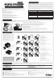
Power
switch
BEC
Connector
Status LED
Set Button
Program Card
Connector
Fan connector
Sensor Connector
BEC
Connector
Power
switch
Cooling Fan
Connector