
- Power Measurement Modem User's Guide

ION 7500 / ION 7600 User’s Guide I/O Expansion Card
Chapter 6 - Hardware Reference Page 179
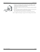
4. Ensure the cover meets the chassis of the base unit. Use the Phillips screwdriver
to replace the two backplate screws with their lock-washers. They must be
installed firmly to preserve transient immunity.
5. Reinstall the Line and Neutral (or DC power) wiring to the Control Power inputs
of the unit.
6. Reconnect all other wiring (or re-enable all other circuits). Close the PT fuses (or
direct voltage input fuses), and open the CT shorting blocks.
7. Turn on power to the meter and verify the correct operation of the unit.
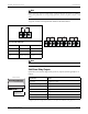
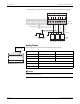
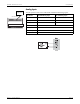
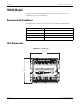
Refer to “Digital and Analog I/O” on page 139 for the settings in these modules.