® MultiModem CDMA Wireless Modem MTCBA-C User Guide
Copyright and Technical Support MultiModem® CDMA User Guide Wireless Modem MTCBA-C S000303J, Revision J Copyright This publication may not be reproduced, in whole or in part, without prior expressed written permission from MultiTech Systems, Inc. All rights reserved. Copyright © 2003-7 by Multi-Tech Systems, Inc. Multi-Tech Systems, Inc.
Table of Contents Contents Chapter 1 – Product Description and Specifications................................................................................................4 Product Description.................................................................................................................................................4 Features..................................................................................................................................................................
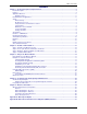
Chapter 1 – Product Description and Specifications Chapter 1 – Product Description and Specifications Product Description The Multi-Tech MultiModem® CDMA is an external data/fax/voice wireless modem. It also supports mobile originated short message service (SMS) and mobile-terminated SMS. It offers standards-based multi-band CDMA2000 1xRTT performance. This ready-to-deploy, standalone modem allows developers to add wireless communication to products with a minimum of development time and expense.
Chapter 1 – Product Description and Specifications Application Overview Application Types With packet data speeds up to 153K bps, the MultiModem CDMA Wireless Modem is targeted at applications that periodically need to send or receive data over a wireless network.
Chapter 1 – Product Description and Specifications Benefits/Features in Applications Short Development Time. The MultiModem CDMA Wireless Modem can make your existing and next generation device, machine, or system, communication-ready without requiring any hardware changes to its design. It actually provides faster time-to-market because it relieves the burden and expense of obtaining network and RF approvals.
Chapter 1 – Product Description and Specifications Safety General Safety The modem is designed for and intended to be used in fixed and mobile applications. “Fixed” means that the device is physically secured at one location and is not able to be easily moved to another location. “Mobile” means that the device is designed to be used in other than fixed locations.
Chapter 1 – Product Description and Specifications Maintenance of Your Modem Your Wireless MultiModem is the product of advanced engineering, design, and craftsmanship and should be treated with care. The suggestions below will help you to enjoy this product for many years. • Do not expose the Wireless MultiModem to any extreme environment where the temperature is above 50ºC or humidity is above 90% noncondensing. • Do not attempt to disassemble the Wireless MultiModem.
Chapter 1 – Product Description and Specifications Specifications General Specifications Power Requirements Mechanical Dimensions & Weight Connectors & Fasteners Operating Temperatures Storage Temperatures Humidity Certifications 5 V to 32VDC 4.3" L x 2.4" W x 0.94" H; 4.2 oz. (11 cm x 6.1 cm x 2.4 cm; 119 g) Antenna Connection type: SMA jack Serial Connector: 15-pin RS232 SUB D female (DE15S) Pins: RS232 link, audio link, RESET Power Connector: 2.
Chapter 1 – Product Description and Specifications Antenna/RF Specifications Frequency Impedance VSWR Typical Radiated Gain CDMA 800 824 to 894 MHz CDMA 1900 1850 to 1900 MHz 50 ohms <2 0 dBi on azimuth plane Interfaces The Wireless MultiModem has several interfaces: LED function indicating operating status External antenna (via SMA connector) Serial and control link (via 15 pins SUB D) Power supply (via 2.5mm miniature power jack) LEDs LED Indicators TD RD CD LS TR PWR Transmit Data.
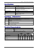
Chapter 1 – Product Description and Specifications RS232 15-Pin Connector Pinout 5 10 15 RS-232 Audio Boot Reset PIN 1 6 2 8 9 7 12 11 13 4 5 10 15 3 14 EIA DCD RX TX DTR GND DSR RTS CTS RI MICROPHONE (+) MICROPHONE (-) SPEAKER (+) SPEAKER (-) BOOT RESET 1 6 11 CCIT 109 104 103 108.2 107 105 106 125 Designation Data Carrier Direct Receive Data (out) Transmit Data Data Terminal Ready Signal Ground Data Set Ready Request to Send Clear to Send Ring Indicator For factory use only.
Chapter 2 – Activation and Installation Chapter 2 – Activation and Installation Step 1 – Activate Your Wireless Account Pre-Configured Multi-Tech Products Each Multi-Tech wireless product has been pre-configured to operate on a wireless network. However, MultiTech offers some models that are not pre-configured. Activate Your Wireless Account Please see the wireless account Activation Notices located on the MultiModem CD.
Chapter 2 – Activation and Installation Serial Cable Connect both sides of the serial and control cable (15-pin Sub D connector on the modem side). Serial & Control Connector To Serial Port of PC Multi-Tech Systems, Inc.
Chapter 2 – Activation and Installation Power Plug the power supply cable into the modem. For two-piece transformer power supply (International). • Connect the AC cord receptacle into the transformer block. • Connect the AC cord plug into the mains power outlet. For one-piece transformer power supply (North America). • Connect between the MultiModem power receptacle and the mains power outlet. For optional direct-DC powering.
Chapter 2 – Activation and Installation Step 3 – Optional – Attach the Modem to a Flat Surface To mount the Wireless MultiModem, do the following: 1. Obtain mounting screws (two are needed) that are appropriate for the surface on which you will mount the modem. For example, one might use two 6-32 self-tapping screws 5/8” in length to mount the unit in a truck to the wall of the cab behind the passenger’s seat. 2. Typically, the unit is mounted against a flat surface into which holes can be drilled.
Chapter 2 – Activation and Installation Step 4 – Install the Modem Driver Introduction Compatibility: The wireless modem is compatible with Windows 2000/2003+, Windows XP, and Linux. Windows: Windows operating systems require a modem driver to be installed. The procedure differs depending on the operating system. This section provides installation procedures for Windows Operating Systems 2000/3000/XP. See the example below for Windows 2003/XP installation.
Chapter 3 – Using Your Wireless Modem Chapter 3 – Using Your Wireless Modem Phone Numbers for the Wireless Modem • Every wireless modem will have its own unique phone number. • The phone number will be given to you by your wireless service provider. Wireless provider implementations may vary. Examples of Useful AT Commands A Note About HyperTerminal In order to verify signal strength and roaming status, you must use a terminal application such as HyperTerminal.
Chapter 3 – Using Your Wireless Modem Establishing a Voice Call • Initiate a voice call Type ATD1234; (Note: Don’t forget the semicolon “;” at the end. This stands for voice calls) Responses: OK (Communication established) CME ERROR : 11 (PIN Code not entered [with +CMEE : 1 mode]) CME ERROR : 3 (Operation not allowed) • Initiate an emergency call Type ATD112; (Note: Don’t forget the semicolon “;” at the end.
Chapter 3 – Using Your Wireless Modem Using Short Message Services (SMS) Send a Short Message to a Specified Number. Type AT+CMGS="8585551212" Then type your message: Please call me soon. The modem may respond with +CMGS: OK Write a Message to Memory. You can store a message to send it at a later date. Type AT+CMGW="8585551212" Type the message. The modem may respond with +CMGW: 4 OK (The message is stored in the index as message 4.
Chapter 3 – Using Your Wireless Modem SMS Examples Send Example: Sending an SMS message at+cpms="MT","MO" (set the read and write locations for SMS) +CPMS:0,30,0,30 OK at+cmgs="7632273726" (send SMS to the number listed in between the quotes) TEST message ONE.
Chapter 3 – Using Your Wireless Modem Internet Access Internet access can be setup in Windows Dial-Up Networking (DUN) of the computer that the wireless modem is serving. Setup procedures will vary according to the type of wireless service provider used. To access Dial-Up Networking on your PC, go to Start > Settings > Network Connections. • For point to point data, a circuit-switched data connection is used. The user can set up DUN to make a conventional V.
Chapter 3 – Using Your Wireless Modem Create Your Dial-Up Connection in Windows XP/2003 1. Click on Start and then click on Control Panel. 2. In the Control Panel, double-click on Network Connections. 3. On the Network Connections screen on the left-hand side under Network Tasks, click on Create a new connection. 4. The New Connection Wizard should appear. It will walk you through setting up your Internet connection. Click on Next > to begin. 5.
Chapter 3 – Using Your Wireless Modem Mobile PhoneTools For initial configuration of your wireless device, Multi-Tech offers a Windows® based mobile PhoneTools Mobile PhoneTools is a communication software program included on your MultiModem CD. You can install this program onto your PC and use it for making Internet connections, voice calls, SMS messaging, and email. This program allows you to use your wireless modem hooked up to your PC as if it were a cell phone. Multi-Tech Systems, Inc.
Chapter 4 – Troubleshooting and Frequently Asked Questions Chapter 4 – Troubleshooting and Frequently Asked Questions Troubleshooting Examples Situation A: The modem does not respond through the serial link If the wireless MultiModem does not respond through the serial link upon an attempted transmission of data or voice signals, see the table below for possible causes and solutions.
Chapter 4 – Troubleshooting and Frequently Asked Questions Frequently Asked Questions I just received this modem, what do I need to do? • You will need to call a carrier and register the ESN number with them. Sprint models (N2) must call Sprint and Verizon models (N3) must call Verizon. Other models, N1 and N4, must contact their provider. • You must then activate the modem: We have Sprint and Verizon models that are preconfigured and just needs to run through the activation steps.
Chapter 4 – Troubleshooting and Frequently Asked Questions When I try to make a data call using ‘ATD’, I get a NO CARRIER response. • Check ‘AT+CEER’ for NO CARRIER reason and look it up in Reference Guide. • Check the number that you are dialing. • Make sure you have CSD service. • Check registration and signal to make sure modem is registered and getting good signal: +CREG, +CSQ. • Make sure you went through the activation procedures correctly.
Chapter 6 – Reference Information Chapter 6 – Reference Information Wireless Modem Reference Information General ETSI contact: Service: ETSI Secretariat F-06921 Sophia Antipolis Cedex, France e-mail: secretariat@etsi.fr The AT commands manual is available on the MultiModem CD and the Multi-Tech web site. Data Cable Diagram – No Voice Multi-Tech Systems, Inc.
Chapter 6 – Reference Information Data Cable Diagram – with Voice Fused DC Power Cable Dimensions How to Change the Fuse The Fused DC power cable is provided when a single unit is purchased. Multi-Tech Systems, Inc.
Appendix A – Warranty and Repairs Appendix A – Warranty and Repairs Multi-Tech Warranty Statement Multi-Tech Systems, Inc., (hereafter “MTS”) warrants that its products will be free from defects in material or workmanship for a period of two, five, or ten years (depending on model) from date of purchase, or if proof of purchase is not provided, two, five, or ten years (depending on model) from date of shipment.
Appendix A – Warranty and Repairs Repair Procedures for International Distributors International distributors should contact their MTS International sales representative for information about the repair of Multi-Tech product(s). Please direct your questions regarding technical matters, product configuration, verification that the product is defective, etc., to our International Technical Support department at +(763)717-5863. When calling the U.S.
Appendix B – WEEE Statement Appendix B - Waste Electrical and Electronic Equipment (WEEE) Statement July, 2005 The WEEE directive places an obligation on EU-based manufacturers, distributors, retailers and importers to takeback electronics products at the end of their useful life. A sister Directive, ROHS (Restriction of Hazardous Substances) complements the WEEE Directive by banning the presence of specific hazardous substances in the products at the design phase.