Operation and Parts Manual Globug MODEL GB2000 Light Tower Mount type balloon light Revision #3 (08/30/12) To find the latest revision of this publication, visit our website at: www.multiquip.com THIS MANUAL MUST ACCOMPANY THE EQUIPMENT AT ALL TIMES.
proposition 65 warning Diesel engine exhaust and some of page 2 —gb2000 balloon light• operation and parts manual — rev.
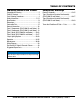
Table of Contents GB2000 BALLOON LIGHT Proposition 65 Warning............................................ 2 Table Of Contents..................................................... 3 Parts Ordering Procedures....................................... 4 Safety Information............................................... 5-12 Specifications......................................................... 13 Dimensions............................................................. 14 Footcandle Plot..........................
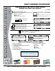
www.multiquip.com Parts Ordering Procedures Ordering parts has never been easier! Choose from three easy options: order via internet (dealers only): best deal! Effective: January 1st, 2006 If you have an MQ Account, to obtain a Username and Password, E-mail us at: parts@multiquip. com. Order parts on-line using Multiquip’s SmartEquip website! ■ View Parts Diagrams ■ Order Parts ■ Print Specification Information To obtain an MQ Account, contact your District Sales Manager for more information.
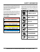
safety information Do not operate or service the equipment before reading the entire manual. Safety precautions should be followed at all times when operating this equipment. Failure to read and understand the safety messages and operating instructions could result in injury to yourself and others.
Safety Information general saFeTy CauTion never operate this equipment without proper protective clothing, shatterproof glasses, respiratory protection, hearing protection, steel-toed boots and other protective devices required by the job or city and state regulations. never operate this equipment when not feeling well due to fatigue, illness or when under medication. never operate this equipment under the influence of drugs or alcohol.
Safety Information lighT ToWer saFeTy danger never operate the equipment in an explosive atmosphere or near combustible materials. An explosion or fire could result causing severe bodily harm or even death. Warning never disconnect any emergency or safety devices. These devices are intended for operator safety. Disconnection of these devices can cause severe injury, bodily harm or even death. Disconnection of any of these devices will void all warranties.
Safety Information engine saFeTy NOTICE danger The engine fuel exhaust gases contain poisonous carbon monoxide. This gas is colorless and odorless, and can cause death if inhaled. The engine of this equipment requires an adequate free flow of cooling air. never operate this equipment in any enclosed or narrow area where free flow of the air is restricted. If the air flow is restricted it will cause injury to people and property and serious damage to the equipment or engine.
Safety Information Fuel saFeTy danger do noT start the engine near spilled fuel or combustible fluids. Diesel fuel is extremely flammable and its vapors can cause an explosion if ignited. alWays refuel in a well-ventilated area, away from sparks and open flames. alWays use extreme caution when working with flammable liquids. do noT fill the fuel tank while the engine is running or hot.
Safety Information TransporTing saFeTy If lifting through pockets, make sure forks of forklift are inserted in pockets as far as possible before lifting. CauTion Before lifting, make sure that light tower parts are not damaged and screws are not loosened or lost. Place chock blocks underneath wheel to prevent rolling while parked. alWays make sure crane or lifting device has been properly secured to lifting hook of the equipment.
Safety Information eleCTriCal saFeTy danger The electrical voltage required to operate the generator can cause severe injury or even death through physical contact with live circuits. Turn generator and all circuit breakers oFF before performing maintenance on the generator. never insert any objects into the output receptacles during operation. This is extremely dangerous. The possibility exists of electrical shock, electrocution or death.
Safety Information baTTery saFeTy danger do noT drop the battery. There is a possibility that the battery will explode. do noT expose the battery to open flames, sparks, cigarettes, etc. The battery contains combustible gases and liquids. If these gases and liquids come into contact with a flame or spark, an explosion could occur. Warning environmenTal saFeTy NOTICE Dispose of hazardous waste properly. Examples of potentially hazardous waste are used motor oil, fuel and fuel filters.
Specifications Table 1. Specifications Model GB2000 Type 1000 W Metal Halide (X2) Number of Bulbs 2 Lamp Current 8.2 A Voltage 238 268 V Lumens 220,000 lm Current 0.87 A Fan Voltage 115 V 12.2 x 12.2 x 39 in Storage (310 x 310 x 990 mm) Dimensions 36 x 36 x 39 in Working (900 x 900 x 990 mm) Total Weight 31 lb (14 kg) Appropriate Generator 3.2 kW and above gb2000 balloon light• operation and parts manual — rev.
dimensions C A C A D B D B E G H F Type 1 Adapter Type 2 Universal Adapter Figure 1. Dimensions Table 2. Dimensions Reference Letter Dimension in. (mm) Reference Letter Dimension in. (mm) A 13.25 (337) E 3.12 (79.3) B 40.0 (1,016) F 9.75 (248) C 35.5 (902) G 8.25 (210) D 34.5 (876) H 4.62 (117) page 14 —gb2000 balloon light• operation and parts manual — rev.
footcandle plot 30 20 10 5 2 1 0.5 0.25 1 grid = 40 ft. Illuminance (Footcandle) 30 20 10 5 2 Diameter (Feet) 9 30 52 65 91 1 0.5 0.25 117 156 232 Figure 2. Footcandle Plot gb2000 balloon light• operation and parts manual — rev.
GENERAL INFORMATION The GB2000 lamp fixture is a difused balloon light that is designed to be mounted and operated on most convential mobile light tower masts. Its design and features permit clean, difused light to be cast uniformly over 232 feet (70.7 meters). The shadow-less lighting dramatically reduces glare in the work area. This type of lighting improves safety and enhances the illuminated area. the GB2000 is ideal for highway work, construction job sites, security support, and special events.
notes gb2000 balloon light• operation and parts manual — rev.
type 1 COMPONENTS (S/N g1900118 and below) 1. Lamp Fixture — Made of heat resistant polyester balloon, with a diameter of 35.5 inches (902 mm) and two 1000 watt metal halide lamps. 2. Locking Pin — Locks the lamp fixture in place when attached to the pole on the bracket. 3. Bracket Plate — Attaches to the Tbar and mast interface of the light tower to allow the GB2000 to be installed. NOTICE 1 This bracket only fits on Multiquip light towers. 4.
type 2 COMPONENTS (S/N g1900119 and above) 1. Lamp Fixture — Made of heat resistant polyester balloon, with a diameter of 35.5 inches (902 mm) and two 1000 watt metal halide lamps. 1 2. Locking Pin — Locks the lamp fixture in place when attached to the pole on the bracket. 3. Balloon Power Cable — Provides AC power to the lamps, fan and baloon inflation circuit. 4. Adapter Plate — Attaches to the T-Bar and mast interface of the light tower to allow the GB2000 to be installed.
type 1 setup (S/N G1900118 and below) PReparation 1. Place the light tower in an area free of dirt and debris with enough clearance as not to interfere with any overhead obstructions. Make sure it is on secure level ground with chock blocks underneath each wheel to prevent the light tower from rolling. 2. For MLT series light towers disconnect the 4-pin power cable (Figure 7) from the 125 VAC twist-lock receptacle on the front panel of the generator.
type 1 setup (S/N G1900118 and below) LAMP BOLT WASHERS MAST T-BAR BRACKET WASHERS NUT INSTALL SCREWS AND NUTS (2) Figure 11. Installing Bracket Figure 9. Lamp Removal assembly 3. Attach junction box (Figure 12) to lamp mounting bracket with the bolts and washers provided. CAUTION Make sure that the T-bar is supported before removing the two screws and nuts to prevent T-Bar from falling off the mast extension. 1. Remove the 2 screws and 2 nuts that secure the T-Bar to the mast extension.
type 1 setup (S/N G1900118 and below) 4. Place the GB2000 lamp fixture (Figure 13) onto the lamp mounting bracket. Lock the lamp fixture in place with the cotter pin. LOCKING PIN LB2000 LAMP FIXTURE Fan/Balloon Power cable Connection 1. Insert the 38 ft. (11.5 meters), 3-prong AC power plug on the fan power cable as shown in Figure 14 into the GFCI power receptacle on the generator. 2. Connect the other end of the fan power cable (quick disconnect end) to the 3-pin AC power cable on the junction box.
type 2 setup (S/N G1900119 and above) PReparation Power Disconnection 1. Place the light tower in an area free of dirt and debris with enough clearance as not to interfere with any overhead obstructions. Make sure it is on secure level ground with chock blocks underneath each wheel to prevent the light tower from rolling. 1. For LT12D light towers, disconnect the negative cable (black) from battery. See Figure 6.
type 2 setup (S/N G1900119 and above) Lamp adapter Plate mounting Installation 1. Remove the adapter plate kit hardware from its container. 2. Before proceeding make sure the light tower mast is in the stow position (down) and the cradle lock/release pin has been inserted and the mast is locked. 3. Attach the lamp adapter plate to the T-Bar as shown in Figure 18. Align adapter plate so that adapter spacer notch fits over screw on T-Bar.
type 2 setup (S/N G1900119 and above) VIEW FROM BACK SIDE BUBBLE LEVEL 2 1 LOCK WASHER (4) HEX NUT (4) 3 SPACER 1 LOW END 2 4 FLUSH W/ T-BAR BOTTOM FLAT WASHER (8) SUPPORT BRACKET (2) BOLT T-BAR BOLT (4) LAMP ADAPTER PLATE T-BAR 1 BACK SIDE UNDERNEATH 3 BOLT 2 2 LAMP ADAPTER PLATE 4 SUPPORT BRACKET J1 NOTES: J2 1 It is important for the adapter SPACER to seat against the T-Bar as shown above. 2 For proper alignment of the adapter plate, use of a bubble level is required. Figure 18.
type 2 setup (S/N G1900119 and above) junction box mounting Lamp mounting 1. Secure the junction box (Figure 19) to the adapter plate using the supplied bolts (2), lock washer (2), and flat washer (2). Tighten mounting bolts securely. 1. Place the GB2000 lamp fixture onto the lamp adapter plate pole as shown in Figure 20. LAMP ADAPTER PLATE T-BAR 2. Insert locking pin into hole opening on pole, then insert cotter pin to lock pin in place. fan power cable connection 1. Insert the 38 ft. (11.
type 2 setup (S/N G1900119 and above) Use Figure 21 as a reference when determining orientation of lamps and receptacles on T-Bar. Figure 21 is looking at the light tower from the rear to the front. J4 GB2000 BALLOON LAMP 2 LAMP 2 (TOP) LAMP 4 J2 LAMP 4 (TOP) J3 LAMP 1 LAMP 3 J1 LAMP 3 (BOTTOM) LAMP 1 (BOTTOM) REAR FRONT Figure 21. Light Tower Orientation View gb2000 balloon light• operation and parts manual — rev.
lamp lighting options Lamp Cable connections On the T-Bar (Figure 22) there are four power receptacles J1, J2, J3 and J4. These receptacles provide AC power to the existing rectangular lamps. When the GB2000 lamp assembly is employed only two of the existing rectangular lamps (bottom lamps recommended) will be available for use. Please reference Figure 22 thru Figure 27 for the various lighting options.
lamp lighting options Table 3. GB2000 LAMP 2 TOP LAMP 4 TOP NOT USED NOT USED 1 2 3 4 LAMP 3 BOTTOM LAMP 1 BOTTOM LT12 LAMP CIRCUIT BREAKERS OFF OFF ON ON MLT LAMP CIRCUIT BREAKERS CB1 CB2 ON OFF CB1 CB2 CB3 CB4 4 Lamps Installed on T-Bar Only GB2000 Operational Figure 23. Option 2 Lighting Configuration gb2000 balloon light• operation and parts manual — rev.
lamp lighting options GB2000 1 2 3 4 LAMP 3 BOTTOM LAMP 1 BOTTOM LT12 LAMP CIRCUIT BREAKERS ON ON ON ON MLT LAMP CIRCUIT BREAKERS CB1 CB2 ON ON CB1 CB2 CB3 CB4 2 Top Lamps Removed GB2000 Operational 2 Bottom Lamps Operational Figure 24. Option 3 Lighting Configuration page 30 —gb2000 balloon light• operation and parts manual — rev.
lamp lighting options GB2000 LAMP 2 TOP LAMP 4 TOP NOT USED NOT USED 1 2 3 4 LAMP 3 BOTTOM LAMP 1 BOTTOM LT12 LAMP CIRCUIT BREAKERS ON ON ON ON MLT LAMP CIRCUIT BREAKERS CB1 CB2 ON ON CB1 CB2 CB3 CB4 4 Lamps Installed on T-Bar GB2000 Operational 2 Bottom Lamps Operational Figure 25. Option 4 Lighting Configuration gb2000 balloon light• operation and parts manual — rev.
lamp lighting options GB2000 LAMP 2 TOP LAMP 4 TOP 1 2 3 4 NOT USED LAMP 3 BOTTOM LAMP 1 BOTTOM LT12 LAMP CIRCUIT BREAKERS ON ON ON ON NOT USED MLT LAMP CIRCUIT BREAKERS CB1 CB2 ON ON CB1 CB2 CB3 CB4 4 Lamps Installed on T-Bar GB2000 Operational 2 Top Lamps Operational Figure 26. Option 5 Lighting Configuration page 32 —gb2000 balloon light• operation and parts manual — rev.
lamp lighting options GB2000 LAMP 2 TOP LAMP 4 TOP 1 2 3 4 LT12 LAMP CIRCUIT BREAKERS ON ON ON ON MLT LAMP CIRCUIT BREAKERS CB1 CB2 ON ON CB1 CB2 CB3 CB4 2 Bottom Lamps Removed GB2000 Operational 2 Top Lamps Operational Figure 27. Option 6 Lighting Configuration gb2000 balloon light• operation and parts manual — rev.
operation Removing balloOn protective cover LT12 LIGHT TOWER CAUTION DO NOT use excessive force when zipping or unzipping the balloon. The possibility exists of the zipper tearing, which would make the balloon unusable. 240 VAC/30A MAIN BREAKER MAIN CIRCUIT BREAKER ON GFCI CIRCUIT BREAKER ON CB1 CB2 CB3 CB4 1. Expose the balloon by unsnapping the buttons and unzipping the protective cover as shown in Figure 28.
operation INFLATING BALLOON AND TURNING ON LAMPs mlt only 5. Next, turn on lamp circuit breakers as referenced in the lamp lighting options section of this manual. 1. On MLT series light towers, reconnect the 4-pin power cable (Figure 31) to the 120 VAC twist-lock receptacle on the front panel of the generator. 6. Secure any unused lamp cables. 7. Raise the light tower mast (Figure 30) to the desired upright height. deflating and storing balloon MLT LIGHT TOWER 1.
maintenance REPLACING LAMP 3. Press the tabs on the lamp holder and push up lamp holder to release it from lamp. Do the same to the lower lamp if necessary. See Figure 35. DANGER Never attempt to replace lamp in a wet place. The possibility exists of electric shock. WARNING LAMP HOLDER Always allow sufficient time for the lamp to cool down before replacing. The possibility exists of severe burns if hot lamp is touched.
maintenance NOTICE Do not use excessive force when screwing the lamp to prevent lamp from breaking. 3. Slide in the new replacement balloon over the top of the lamp guard assembly. See Figure 40. 6. Secure lamp holder on top of the lamp. 7. Reinstall lamp guard. 8. Pull down balloon and zip the bottom zipper to cover lamp. INSTALL NEW BALLOON REPLACING BALLOON 1. Unzip the top and bottom of the balloon. See Figure 38. Figure 40. Replacing Balloon 4. Zip up the top and bottom of the new balloon.
maintenance SYMPTOM Lamp does not light. Lamp only lights for a short time. Balloon does not inflate. Table 4. Troubleshooting POSSIBLE PROBLEM Is plug disconnected? Is generator power switched off? Is lamp loose? Is power connector disconnected or loose? Is model of lamp incompatible? Is ambient temperature too high more than 104° F (40° C)? Is fan motor not working properly? Is balloon cloth defective? SOLUTION Plug in correctly. Turn on switch. Screw lamp securely into socket.
wiring diagram RED F M WHITE SOCKET WHITE THERMO F UPPER LAMP M CABLE (THERMO) 2 CP F WHITE BLACK 2 x 1000 WATT METAL HALIDE LAMP CABLE (THERMO) 1 CP M M F CABLE (LAMP) 2 CP WHITE CABLE (THERMO) 4 CP F THERMO SOCKET LOWER LAMP M F BLACK CABLE (THERMO) 3 CP M M WHITE CABLE NO. RED FLANGE 1 2 M M M F F F F GREEN FAN MOTOR BLACK BLACK BLACK BLACK BLACK F M F M BLACK CABLE NO.
Explanation of Code in Remarks Column The following section explains the different symbols and remarks used in the Parts section of this manual. Use the help numbers found on the back page of the manual if there are any questions. NOTICE The contents and part numbers listed in the parts section are subject to change without notice. Multiquip does not guarantee the availability of the parts listed. sample parTs lisT no. 1 2% 2% 3 4 parT no. parT name QTy. remarKs 12345 BOLT .....................1 .....
Suggested Spare Parts gb2000 bALLOON LIGHT 1 to 3 units Qty. P/N Description 2............E000080700..........LAMP 2............A100085100..........BALLOON CLOTH CP 3............A400038300..........FILTER NOTICE Part numbers on this Suggested Spare Parts list may supersede/replace the part numbers shown in the following parts lists. gb2000 balloon light• operation and parts manual — rev.
electrical assy. 58 1 3 45 43 54 40 46 49 26 26 26 11 16 12 29 13 28 34 2 4 2 50 35 53 10 52 22 21 21 19 24 49 14 32 7 26 33 6 26 25 7 14 51 36 18 37 46 48 47 20 8 20 10 9 14 11 11 62 42 26 15 43 59 30 12 12 31 59 13 13 38 60 14 60 39 1 14 44 27 60 5 57 58 17 41 26 56 60 60 61 23 60 61 page 42 —gb2000 balloon light• operation and parts manual — rev.
electrical assy. NO. 1 2 3 4 5 6 7 8 9 10 11 12 13 14 15 16 17 18 18 19 20 21 22 23 24 25 26 27 28 29 30 31 32 33 34 35 36 37 38 39 40 41 42 43 44 45 PART NO.
electrical assy. (CONTINUED) 58 1 3 45 43 54 40 46 49 26 26 26 11 16 12 29 13 28 34 2 4 2 50 35 53 10 52 22 21 21 19 24 49 14 32 7 26 33 6 26 25 7 14 51 36 18 37 46 48 47 20 8 20 10 14 9 14 13 11 11 62 42 38 26 15 43 59 30 12 12 31 59 13 60 39 60 1 14 44 27 60 5 57 58 17 41 26 56 60 60 61 23 60 61 page 44 —gb2000 balloon light• operation and parts manual — rev.
electrical assy. (CONTINUED) NO. 46 47 48 49 50 51 52 53 54 55 56 57 58 59 59 60 61 62 PART NO. 1411200110 A400252301 A400252401 0023103006 2204220130 E000103600 1800001000 A200075601 A400244701 A400244801 A200018000 A400199500 A300211600 A300221900 A300221901 0023405010 0023404006 E000009701 PART NAME QTY. REMARKS THERMOSTAT 2 CABLE (THERMO) 1 CP M................................1................INCLUDES TERMINAL CABLE (THERMO) 2 CP F.................................1................
BRACKET AND J-BOX assy. (S/N G1900118 and BELOW) TYPE 1 ADAPTER 8 18 14 13 11 1 6 2 10 11 11 12 3 4 16 5 17 7 15 7 9 page 46 —gb2000 balloon light• operation and parts manual — rev.
BRACKET AND J-BOX assy. (S/N G1900118 and BELOW) NO. 1# 2# 3# 4# 5# 6# 7# 8# 9# 10# 11# 12# 13# 14# 15# 16# 17 18 PART NO. A200076200 A400241000 A300215200 0023303008 0023303012 0033103000 A300215300 A200076300 A300215500 0033104000 0024304008 E000072600 E000099100 0013510025 E000099200 A300215400 A000033600 10176 PART NAME QTY. REMARKS JUNCTION BOX (RELAY) 1 COVER (RELAY) 1 CABLE (BALLOON) 2 CP...................................1................
BRACKET AND J-BOX assy. (S/N G1900119 and ABOVE) TYPE 2 UNIVERSAL ADAPTER 13 14 17 23 8 6 1 SPARE PART 19 22 22 11 20 2 11 12 10 7 17 3 18 4 16 7 5 21 4 15 5 15 9 page 48 —gb2000 balloon light• operation and parts manual — rev.
BRACKET AND J-BOX assy. (S/N G1900119 and ABOVE) NO. 1# 2# 3# 4# 5# 6# 7# 8# 9# 10# 11# 12# 13# 14# 15# 16# 17# 18# 19# 20# 21# 22# 23 PART NO. A200084201 A400241000 A300215200 0023303008 0023303012 0033103000 A300215300 A100088602 A300255600 A400288000 0024304008 E000072600 0013112130 0013510025 E000099200 A300255700 0043112000 0043212000 A400287902 0023205015 0033112000 A400287801 A000039000 PART NAME QTY.
Terms and Conditions of Sale — Parts paymenT Terms 5. Parts must be in new and resalable condition, in the original Multiquip package (if any), and with Multiquip part numbers clearly marked. 6. The following items are not returnable: Multiquip reserves the right to quote and sell direct to Government agencies, and to Original Equipment Manufacturer accounts who use our products as integral parts of their own products. a. speCial expediTing serviCe Terms of payment for parts are net 30 days.
notes gb2000 balloon light• operation and parts manual — rev.
Operation and Parts Manual HERE’S HOW TO GET HELP PLEASE HAVE THE MODEL AND SERIAL NUMBER ON-HAND WHEN CALLING United StateS Multiquip Corporate Office 18910 Wilmington Ave. Carson, CA 90746 Contact: mq@multiquip.com MQ Parts Department Tel.