OPERATION AND PARTS MANUAL GLOBUG SERIES MODEL GB114BS/BP LIGHTING SYSTEM Revision #3 (01/06/09) To find the latest revision of this publication, visit our website at: www.multiquip.com THIS MANUAL MUST ACCOMPANY THE EQUIPMENT AT ALL TIMES.
TABLE OF CONTENTS MQ GLOBUG LIGHTING SYSTEM Table of Contents ..................................................... 2 Parts Ordering Procedures ...................................... 3 Safety Information ................................................ 4-7 Specifications .......................................................... 8 Dimensions (GB114BS) .......................................... 9 Dimensions (GB114BP) ........................................ 10 Floodlight Footcandle Plot ....................
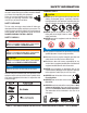
www.multiquip.com PARTS ORDERING PROCEDURES Ordering parts has never been easier! Choose from three easy options: Effective: January 1st, 2006 Best Deal! Order via Internet (Dealers Only): If you have an MQ Account, to obtain a Username and Password, E-mail us at: parts@multiquip.com. Order parts on-line using Multiquip’s SmartEquip website! ■ View Parts Diagrams ■ Order Parts ■ Print Specification Information To obtain an MQ Account, contact your District Sales Manager for more information.
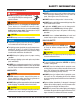
SAFETY INFORMATION Do not operate or service the equipment before reading the entire manual. Safety precautions should be followed at all times when operating this equipment. Failure to read and understand the safety messages and operating instructions could result in injury to yourself and others. SAFETY MESSAGES The four safety messages shown below will inform you about potential hazards that could injure you or others.
SAFETY INFORMATION LIGHTING SYSTEM SAFETY DANGER NEVER use lighting system in rain, snow or areas of high humidity that could generate electrical storms. WARNING NEVER disconnect any emergency or safety devices. These devices are intended for operator safety. Disconnection of these devices can cause severe injury, bodily harm or even death. Disconnection of any of these devices will void all warranties. CAUTION NEVER attempt service on a running machine.
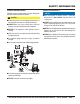
SAFETY INFORMATION GENERATOR SAFETY Power Cord/Cable Safety If using a generator to power lighting system, refer to applicable generator manual safety information section. NEVER let power cords or cables lay in water. ELECTRICAL SAFETY NEVER use damaged or worn cables or cords. Inspect for cuts in the insulation DANGER Lighting system is equipped with a ground pin on the power plug. For your protection, ALWAYS complete the grounding path.
SAFETY INFORMATION LOADING AND UNLOADING If lighting system is equipped with a transport lifting hook, refer to the following safety information. CAUTION Before lifting, make sure that lighting system parts are not damaged and screws are not loosened or lost. ALWAYS make sure crane or lifting device has been properly secured to lifting hook of the equipment. NEVER lift the equipment while lighting system is running. Make sure the mast is completely lowered before lifting the lighting system.
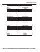
SPECIFICATIONS Table 1. Specifications GloBug Lighting System Model Input Voltage Ballast Frequency Max. Current Lamp Lamp Type Lumens Light Coverage (360°) Surface Temperature (Longitudinal) Surface Temperature (Transversal) Fan Motor Balloon Fan Motor Max. Current Pressure Balloon Diameter Material Heat Resisting Temperature Melting Temperature Internal Temperature of Balloon Water Resistance Weight GB114BS GB114BP GB114BS/GB114BP 120 VAC Magnetic Ballast 60 Hz 60 Hz Single-Phase 9.
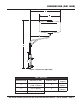
DIMENSIONS (GB114BS) Figure 1. Dimensions (GB114BS) Table 2. Dimensions Reference Letter Dimension in. (mm.) Reference Letter A 88.0 -108.0 in. (2,230 - 2,730 mm.) D B 59 in. (1,500 mm.) E C 47.16 in. (1,200 mm.) Dimension in. (mm.) 35.00 in. (900 mm.) 35.00 in. (900 mm.) GB114BS/BP GLOBUG LIGHTING SYSTEM • OPERATION AND PARTS MANUAL — REV.
DIMENSIONS (GB114BP) B A Figure 2. Dimensions (GB114BP) Table 3. Dimensions Reference Dimension in. (mm.) Letter A 28.00 in. (712 mm.) B 47.16 in. (1,200 mm.) PAGE 10 — GB114BS/BP GLOBUG LIGHTING SYSTEM • OPERATION AND PARTS MANUAL — REV.
FOOTCANDLE PLOT 360° Coverage .5 1 2 5 10 Values listed as footcandles Scale: Grid = 50 ft. (15.25 meters) Figure 3. Floodlight Footcandle Plot (BAL-115 Drum Shaped) GB114BS/BP GLOBUG LIGHTING SYSTEM • OPERATION AND PARTS MANUAL — REV.
GENERAL INFORMATION The Multiquip GloBug GB114BS, and GB114BP are general purpose portable glare-free lighting systems. Typical applications for these types of lighting systems include construction sites, emergency road crews and backyard parties. BALLOON ENVELOPES The GloBug lighting system can be configured with a variety of balloon envelopes (canopy). Please contact the MQ sales department for the balloon of your choice. The GloBug GB114BS and GB114BP shipped from the factory with the drum type balloon.
NOTES GB114BS/BP GLOBUG LIGHTING SYSTEM • OPERATION AND PARTS MANUAL — REV.
COMPONENTS Figure 5. Major Components PAGE 14 — GB114BS/BP GLOBUG LIGHTING SYSTEM • OPERATION AND PARTS MANUAL — REV.
COMPONENTS Figure 5 shows the location of the components for the GloBug lighting system. The function of each component is described below: 1. Lamp Guard — This guard (cage) protects the lamp from being hit by objects. 2. Lamp — 1000 watt metal-halide type lamp. Replace only with MQ recommended type lamp. Always allow a sufficient amount of time for the lamp to cool down before changing. 3. Fan Motor (Blower) — This electric motor is responsible for inflating the balloon. It will supply a pressure of 31.
SETUP NOTICE The pole clamp assembly used in this setup procedure is a dual type clamp. One side of the clamp is for the attachment of the main pole of the lighting system. The other side of the clamp is used for the attachment of a support pole that is usually connected to a piece of equipment such as a paver. 9. Using 17 mm wrench, tighten both bolts (M) on the offset adapter clamp (K) securely. 10. Place lamp assembly (N) onto offset pole (B). Tighten T-handle bolt (O) securely.
SETUP REMOVING THE PROTECTIVE COVERING CONNECTING POWER CABLE 1. Expose the balloon by pulling down on the velcro tab and unzip the protective cover as shown in Figure 7. 1. Connect 16.4 ft. (5 meters) lamp power cable (Figure 8) to the balloon power cable. STEP 1 UNZIP PROTECTIVE COVER PROTECTIVE COVER BALOON BALLOON POWER CABLE LAMP ASSEMBLY STEP 2 FOLD PROTECTIVE COVER INTO ITSELF VELCRO TAB BALLOON FULLY EXPOSED BALLAST LAMP POWER CABLE Figure 8. Connecting Lamp Power Cable 2.
OPERATION RAISING THE EXTENSION POLE APPLYING POWER 1. Before raising the extension pole, make sure the T-handle bolt lock (Figure 6-O) is securely tightened. This will prevent the balloon/lamp assembly from falling off. In addition make sure that the lamp power cable is connected to the mating end of the power source cable. 1. Make sure the power ON/OFF switch (Figure 10) located near the bottom of the ballast is in the OFF position. 2. Raise extension pole (Figure 6-L) to desired height.
OPERATION/SHUTDOWN SHUTDOWN NOTICE ALWAYS Make sure ballast is securely mounted to a surface where it will not move, slip or fall. This will prevent severe damage to the ballast. 1. Place the ON/OFF switch on the ballast to the OFF position. The balloon should begin to deflate and the lamp turns off. 3. Place the ON/OFF switch (Figure 12) on the ballast in the ON position. 2. If using a portable generator, shut-down the generator as referenced in the "Shutdown Section" of the supplied generator manual.
STORAGE NOTICE Allow a sufficient amount of time (15-20 minutes) for the lamp to cool down . The possibility exists of the balloon getting burned (touching the lamp). 2. Remove both S-type hooks (Figure 9) on the lamp power cable from the cable support holes on the offset pole. 3. Unzip the zipper on the protective cover (Figure 14), and pull down cover over balloon/lamp assembly. ZIPPER LOWERING THE EXTENSION POLE 1. Using the supplied 19 mm wrench, loosen extension clamp bolt (Figure 6-Q). 2.
MAINTENANCE CAUTION CAUTION Before performing any maintenance procedures, be sure to READ the lamp, balloon, and general safety guidelines in this manual. Failure to read and understand these safety guidelines could cause severe equipment damage and bodily harm. REMOVING THE LAMP ASSEMBLY 1. Allow lamp (Figure 17) 15-20 minutes to cool before changing. DO NOT use excessive force when zipping or unzipping the balloon. The possibility exists of the zipper tearing, which would make the balloon unusable.
MAINTENANCE 3. Push down and hold the lamp holder (spring loaded) away from the lamp (Figure 21). Unscrew the lamp (turn counterclockwise) from the lamp socket. BALLOON PIPE FRAME LAMP SOCKET LAMP HOLDER SNAP LAMP GUARD INTO PIPE FRAME Figure 23. Installing the Lamp Guard PUSH DOWN TO REMOVE LAMP TURN COUNTERCLOCKWISE Figure 21. Removing the Lamp INSTALLING A NEW LAMP 1. When installing a new lamp (Figure 22) use only MQ recommended type lamp. See parts section of this manual.
MAINTENANCE 5. Install a new filter over the brace as shown in Figure 28. Be sure to align the cut of the filter over the brace. CAUTION DO NOT replace filter immediately, allow a sufficient amount of time for the lamp assembly to cool down before changing filter BRACE FILTER FILTER REPLACEMENT 1. Remove the balloon as described in the "Removing the Lamp/Balloon" section. 2. Disconnect the lamp power cable (Figure 5). CUT 3. Rotate the balloon/lamp base assembly so that the filter is facing upwards.
MAINTENANCE B1 B2 P5 P6 E1 P4 P3 L5 P1 L1 L4 E3 B3 P2 L3 L2 B4 E2 Figure 30. Maintenance Check Points PAGE 24 — GB114BS/BP GLOBUG LIGHTING SYSTEM • OPERATION AND PARTS MANUAL — REV.
MAINTENANCE For a prolonged life cycle an extended quality follow the recommended GloBug lighting system service guidelines as referenced in Figure 30 and Table 4. Figure Lamp Balloon Electric Pole L1 L2 L3 L4 L5 B1 B2 B3 B4 E1 E2 E3 P1 P2 P3 P4 P5 P6 ❖ - Daily Check Table 4.
TROUBLESHOOTING (LAMP) Practically all breakdowns can be prevented by proper handling and maintenance inspections, but in the event of a breakdown, please take a remedial action following the diagnosis based on the Lamp Troubleshooting (Table 5) information shown below. If the problem cannot be remedied, please leave the unit just as it is and consult or company's service department. Table 5.
WIRING DIAGRAM 120 VAC, 60Hz INPUT BALLAST POWER CABLE P1 ORANGE 208 VAC PURPLE NOT USED T1 240 VAC 277 VAC BLACK TRANSFORMER (BALLAST) BLK (LINE) CAP COM 120 VAC RED/BLK YEL YEL BLK/YEL 24uF @480 VDC WHT (NEUTRAL) GRN GRN CAPACITOR S1 CHASSIS GND C1 OFF/ON SWITCH RED BLK RED SPLICE FRONT VIEW BALLAST RECEPTACE (FEMALE) BLK J1 BLK GRN 2 1 4 3 RED WHT BLK 1000 WATT METAL HALIDE LAMP MALE RED (HOT) RED DS1 WHT (NEUTRAL) WHT LAMP POWER CABLE (W1) BUZZER GRN S2 S3 B1 MIC
VOLTAGE MEASUREMENTS DANGER Be careful when performing voltage measurements. The possiblity exists of electrical shock if fingers make contact with connector pins, thus causing bodily harm or even death. NEVER allow multimeter test leads to make contact with each other. The possibility exists of electrical short causing severe damage to the equipment, bodily harm, electrocution, and even death! VOLTAGE MEASUREMENT (BALLAST NO-LOAD) 1.
VOLTAGE MEASUREMENTS Figure 32. Voltage Measurements GB114BS/BP GLOBUG LIGHTING SYSTEM • OPERATION AND PARTS MANUAL — REV.
EXPLANATION OF CODE IN REMARKS COLUMN The following section explains the different symbols and remarks used in the Parts section of this manual. Use the help numbers found on the back page of the manual if there are any questions. The contents and part numbers listed in the parts section are subject to change without notice. Multiquip does not guarantee the availability of the parts listed. * * Numbers Used - Item quantity can be indicated by a number, a blank entry, or A/R.
SUGGESTED SPARE PARTS GB114BP/BS GLOBUG LIGHTING SYSTEM 1 to 3 units QTY. P/N DESCRIPTION 2............LB41827 ...............LAMP 2............A300033800 .........BALLAST 2............A300038400 .........CAPACITOR 22 µF @ 480 VDC 2............1654000230..........BALLOON PATCH KIT GB114BS/BP GLOBUG LIGHTING SYSTEM • OPERATION AND PARTS MANUAL — REV.
NAMEPLATE AND DECALS DANGER To avoid accident or injury NEVER exceed a travel speed of 5 MPH when using lighting system on a mobile equipment. DCL 1001 1 2 DANGER To avoid accident or injury ALWAYS make certain hardware is securely fastened on pipe clamps. DCL1002 DANGER 3 To avoid accident or injury ALWAYS make certain hardware is securely fastened on pipe clamps. 4 DCL1002 DANGER WARNING ELECTRICAL SHOCK HAZARD BURN HAZARD 2 To prevent burns, NEVER touch lamp while lamp is on.
NAMEPLATE AND DECALS NO. 1 2 3 4 5 6 7 8 9 10 11 12 13 14 15 PART NO. DCL1001 DCL1002 DCL416 DCL417 DCL418 DCL415 DCL409 DCL404 DCL413 DCL427 0800628504 DCL424 DCL410 35137 PART NAME QTY. REMARKS DECAL; DANGER, TRAVEL SPEED ...............................1 ....... REPLACES P/N A400084000 DECAL; DANGER, PIPE CLAMP 1 DECAL; DANGER, ELECTRICAL SHOCK HAZ. 1 DECAL; WARNING, BURN HAZARD (LAMP) 1 DECAL; DANGER, HIGH VOLTAGE 1 DECAL; BURN HAZARD (BALLAST) 1 NAMEPLATE ..............................................
BALLAST ASSEMBLY. S/N G30001 27 A 20 6 23 3 17 26 26 22 1 24 25 18 28 17 22 7 17 26 23 20 10 14 15 22 4 16 9 29 8 11 12 13 PAGE 34 — GB114BS/BP GLOBUG LIGHTING SYSTEM • OPERATION AND PARTS MANUAL — REV.
BALLAST ASSEMBLY. S/N G30001 NO. A 1$ 3$ 4$ 6$ 7$ 8$ 9$ 10$ 11$ 12$ 13 14$ 15$# 16$ 17 18 20 22 23 24$ 25$ 26$ 27$ 28$% 29$ PART NO. A000017700 A100010202 A300033800 A200016900 A200018100 A400035200 0020104015 A400037600 0020503012 A400038200 A400035800 A300034700 A400037500 E000036400 1406000700 0023304008 A300034800 0013510025 0033104000 A400034100 A200018200 0023305090 0023304012 A100013500 19598 1367020430 PART NAME QTY. REMARKS BALLAST ASSY. ...........................................................
BALLAST ASSEMBLY. S/N G30002 & ABOVE A 17 1 16 13 4 2 15 15 12 11 18 19 20 11 13 21 15 22 9 16 3 10 23 5 14 6 15 8 PAGE 36 — GB114BS/BP GLOBUG LIGHTING SYSTEM • OPERATION AND PARTS MANUAL — REV.
BALLAST ASSEMBLY. S/N G30002 & ABOVE NO. A 1$ 2$ 3$ 4$ 5$ 6$ 8$ 9$ 10$ 11$ 12 13 14$ 15$ 16$ 17$ 18$ 19$% 20$ 21$ 22$ 23$ PART NO. A000017702 A100015401 A300033800 A200020904 A200018100 A400079400 0023303008 A300066700 A400037502 1406000700 0023306012 A300083600 E000028200 E000045000 0023304012 0013510025 A100013500 0023305090 A300038400 A200018200 0033104000 0043204000 1367020430 PART NAME QTY. REMARKS BALLAST ASSY. ............................................................. 1.........
FAN BLOWER/LAMP BASE ASSEMBLY PAGE 38 — GB114BS/BP GLOBUG LIGHTING SYSTEM • OPERATION AND PARTS MANUAL — REV.
FAN BLOWER/LAMP BASE ASSEMBLY NO. A PART NO.
BALLOON/LAMP GUARD ASSEMBLY 1 2 21 20 3 3A 4 BALLOON PATCH KIT A 8 5 6 7 19 8 9 18 17 10 16 10 15 11 11 14 10 17 12 10 13 11 11 PAGE 40 — GB114BS/BP GLOBUG LIGHTING SYSTEM • OPERATION AND PARTS MANUAL — REV.
BALLOON/LAMP GUARD ASSEMBLY NO. A PART NO. A000017600 A A000017601 1 1# 2# 3# 3A# 4# 5# 6# 7# 8# 9# 10# 11# 12# 13# 14# 15# 16# 17# 18# 19$ 19% 20 21 GBBAL120 GBBAL115D 0014808025 A100028505 A300060202 2204220130 2204500230 1800001000 2204500130 A100010800 A300026901 0024304008 2204400130 A300032700 2204231730 E000009800 E000009601 0025304025 2204231530 A400038400 A400038500 A400038501 GBBALD1 1654000230 PART NAME QTY. REMARKS BALLOON ASSY .............................................................
OFFSET POLE ASSEMBLY 1 A 7 3 5 6 10 28 9 4 12 2 11 11 12 22 13 21 13 14 15 14 17 12 16 14 17 8 19 20 29 18 24 21 22 14 15 14 23 16 12 14 17 27 19 29 2 26 18 25 24 PAGE 42 — GB114BS/BP GLOBUG LIGHTING SYSTEM • OPERATION AND PARTS MANUAL — REV.
OFFSET POLE ASSEMBLY NO. A 1$ 2$ 3$ 4$ 5$ 6$ 7$ 8$ 9$ 10$ 11$ 12$# 13$# 14$# 15$# 16$# 17$# 18$# 19$# 20$# 21$# 22$# 23$# 24$# 25$ 26$ 27$ 28$ 29$ PART NO. A000018200 A200019103 A200018303 0013512045 0014210025 0013510025 0043110026 E000028100 A300040904 A200021902 0013112055 0043212000 0043112000 0030810000 0043110000 E000028300 E000028401 A400067600 A400061500 A300053901 A200025203 A300043601 E000042101 E000042001 0054010060 A400082101 0033206000 0040825000 0013112065 A000025300 PART NAME QTY.
TERMS AND CONDITIONS OF SALE — PARTS PAYMENT TERMS 5. Parts must be in new and resalable condition, in the original Multiquip package (if any), and with Multiquip part numbers clearly marked. 6. The following items are not returnable: Terms of payment for parts are net 30 days. FREIGHT POLICY All parts orders will be shipped collect or prepaid with the charges added to the invoice. All shipments are F.O.B. point of origin.
NOTES GB114BS/BP GLOBUG LIGHTING SYSTEM • OPERATION AND PARTS MANUAL — REV.
OPERATION AND PARTS MANUAL HERE’S HOW TO GET HELP PLEASE HAVE THE MODEL AND SERIAL NUMBER ON-HAND WHEN CALLING UNITED STATES Multiquip Corporate Office 18910 Wilmington Ave. Carson, CA 90746 Contact: mq@multiquip.com MQ Parts Department Tel. (800) 421-1244 Fax (800) 537-3927 Mayco Parts 800-427-1244 310-537-3700 Fax: 800-672-7877 Fax: 310-637-3284 Warranty Department 800-306-2926 310-537-3700 Fax: 800-672-7877 Fax: 310-637-3284 Service Department 800-421-1244, Ext. 279 310-537-3700, Ext.