MT5600BA/BL Series MT5600BA–V.92 MT5600BA–V.90 MT5600BL–V.
MultiModemII User Guide MT5600BA–V.92, MT5600BA–V.90, MT5600BL–V.90 P/N S000276E Revision E ©2002-2004 by Multi-Tech Systems, Inc. All rights reserved. This publication may not be reproduced, in whole or in part, without prior expressed written permission from Multi-Tech Systems, Inc. Multi-Tech Systems, Inc. makes no representations or warranties with respect to the contents hereof and specifically disclaims any implied warranties of merchantability or fitness for any particular purpose.
MultiModemII User Guide Table of Contents Table of Contents Chapter 1 - Description and Features ......................................................................... 5 Product Description .............................................................................................. 5 About AT Commands ........................................................................................... 5 Features ...................................................................................................
MultiModemII User Guide Table of Contents Chapter 7 - Troubleshooting ..................................................................................... 41 None of the Indicators Light ............................................................................... 41 The Modem Does Not Respond to Commands .................................................. 42 The Modem Cannot Connect When Dialing ....................................................... 43 The Modem Disconnects While Online ..............
Chapter 1 - Description and Features Descript iptiion and Chapter 1 - Descr ipt ures es Featur Congratulations on your purchase of the MultiModemII modem. You have acquired one of the finest intelligent data/fax modems available today from one of the world’s oldest modem manufacturers: MultiTech Systems, Inc. This user guide will help you install, configure, test and use your modem. Product Descr ipt Descript iptiion This modem supports two-wire and/or four-wire leased lines.
Chapter 1 - Description and Features Saf et y War ning s afet ety arning nings • • • • • • • • Use this product only with UL- and CUL-listed computers. To reduce the risk of fire, use only 26 AWG or larger telephone wiring. Never install telephone wiring during a lightning storm. Never install a telephone jack in a wet location unless the jack is specifically designed for wet locations.
Chapter 2 - Installation Instal alla lat Chapter 2 - Inst al la t i on Step 1 - C onne ct tthe he Mod em to Your Sy stem Co nnect Modem System Turn off your computer. Placing the modem in a convenient location, connect it to your computer’s serial port, to the telephone line, to your leased line, to AC power, and, optionally, to your telephone. PHONE LINE LEASED EIA RS232C VOLUME POWER or MultiModemII connections with V.92 transformer and V.90 transformer.
Chapter 2 - Installation nnect Fourour-W ire Le Conne ct tthe he F ourW ir eL eased Line MT5600BL Only – Plug one end of a four-wire phone cable into the modem's LEASED jack; connect the other end to a four-wire leased line wall jack or terminals. Modems with a leased-line jack support the dial backup feature. For dial backup operation, plug one end of your dialup modular phone cable into the modem’s LINE jack and the other end into a PSTN wall jack.
Chapter 2 - Installation Step 2 - Inst al he Mod em Dr iv er Instal alll tthe Modem Driv iver If you use Windows 98/Me/NT 4.0/2000/XP; you must install the modem driver. The drivers are installed easily since Windows supports Plug-and-Play. Inst al ling tthe he Mod em Dr iv er ffo or W ind ows 98/Me/2000/ Instal alling Modem Driv iver indo XP 1. Make sure your modem is connected properly, and then turn on your computer. Windows should detect your new modem and open the Install New Modem wizard.
Chapter 2 - Installation Step 3 - Set t ing Your C ount ry o rR eg od e Sett Count ountr or Reg egiion C Cod ode (MT5600BA (MT5600B A–V.92 Only) The MT5600BA-V.92 modem is a global modem - it can be used all over the world. However, countries or regions vary in their requirements for how a modem functions. Therefore, you must configure yours to match the defaults of the country or region in which you are using it.
Chapter 2 - Installation Co mmands Using AT C omm ands If you are comfortable using AT commands, you can use them to configure your modem. You must enter these commands in your communication program's terminal window. You can use a communication program such as PhoneTools. See Step 4 below. How to Change the Country/Region Code 1.
Chapter 3 - Using the Front Panel Fro Panel Chapter 3 - Using tthe he Fr ont P anel Like any modem, your Multi-Tech modem operates only under the control of a communication program, such as the PhoneTools program included with the modem. It also operates under other general-purpose data communication programs, such as Windows Terminal and HyperTerminal. For information on how to use the modem with the communication program of your choice, please refer to the program’s documentation.
Chapter 3 - Using the Front Panel Liquid Cr yst al Disp la y (L CD) Cry stal Displa lay (LCD) The MultiModemII’s backlit liquid crystal display (LCD) has two functions: to display the current status of the modem and to display configuration menus, which are selected using the four pushbuttons on the front panel. Opt ct Optiion Sele Select ctiion To select most configuration options, simply display the option in the LCD, and then press the Enter button to select it.
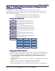
Chapter 3 - Using the Front Panel Menu O ver v i ew Ov erv Trunks Limbs Status = , Branches Status = Idle , Twigs Manual Orig.? , ,Ent Manual Answer? , ,Ent 49333,Async,Lapm , Disconnect? Current Settings= , PSTN PSTN? ( automatic selection ) Status = Online Basic Options , , Advanced Options , , Remote Config. , , Diagnostics , , Phone Number Memory , , Caller I.D.
Chapter 3 - Using the Front Panel St at us Tr unk Sta Trunk The Status Trunk shows the current operating status of the modem. Limb changes are automatic, but certain options can be accessed by pressing the Æ button. Note that when the modem is online, pressing the Æ button shows the connect status, including the data speed, connection type, and compression type. Limbs Twigs If Idle If Online Multi-Tech Systems, Inc.
Chapter 3 - Using the Front Panel B asi c Opt unk asic Optiions Tr Trunk Use the Basic Options Trunk to configure the modem’s basic operating conditions. When entering a number, use the ÇÅ and È buttons to scroll through a list of digits and characters. To go to the next position, press the Æ button. To back up or to exit without dialing, press the Æ button several times. Limbs Branches Twigs Current Setting Async AT Async, XCLK? Async, SLAV? Continued on next page Multi-Tech Systems, Inc.
Chapter 3 - Using the Front Panel B asi c Opt unk ont inued asic Optiions Tr Trunk unk,, c co ntinued Limbs Branches Twigs Continued from previous page Multi-Tech Systems, Inc.
Chapter 3 - Using the Front Panel Adv anc ed Opt unk dvanc anced Optiions Tr Trunk Use the Advanced Options Trunk to configure RS-232, dial backup, and callback security options. When entering a number or password, use the ÇÅ and È buttons to select a character or digit. To go to the next position, press the Æ button. To backspace or to exit, press the Æ button several times. Limbs Branches Twigs Continued on next page Multi-Tech Systems, Inc.
Chapter 3 - Using the Front Panel Adv anc ed Opt unk ont inued dvanc anced Optiions Tr Trunk unk,, c co ntinued Limbs Branches Twigs Continued from previous page Multi-Tech Systems, Inc.
Chapter 3 - Using the Front Panel Remote C onf ig ur at ion Opt unk Co nfig igur ura Optiions Tr Trunk Use the Remote Configuration Options Trunk to enable or disable remote configuration on the modem, and to change the password. When entering the password, use the ÇÅ and È buttons to scroll through the alphabet. To go to the next character position, press the Æ button. To backspace or to exit, press the Æ button several times.
Chapter 3 - Using the Front Panel Pho ne Number Memo r y Opt unk Phone Memor Optiions Tr Trunk The MultiModemII can store up to four telephone numbers for speed dialing. Use the Phone Number Memory Options Trunk to store, list, and dial these numbers. When entering a number, use the ÇÅ and È buttons to scroll through the available digits and dialing commands. To go to the next position, press the Æ button. To backspace or to exit, press the Æ button several times.
Chapter 3 - Using the Front Panel Menu Opt Optiions This section describes important LCD screens and options. Many, but by no means all, of the options have AT command equivalents. Sta St at us Status screens display the current status of the modem. Though limb changes are automatic, certain options can be selected by pressing the Æ button. STATUS = IDLE. The modem is ready but inactive. This screen appears when the modem is first turned on, and is the starting point for accessing all other screens.
Chapter 3 - Using the Front Panel B asi c Opt asic Optiions The following screens are used to configure the modem’s basic operating conditions. ONLINE OPTIONS. The following screens are used to configure the online operation of the modem: LINE TYPE OPTIONS. Use the Æ and Enter buttons to select from the following line types: dial-up (PSTN), two-wire leased line originate or answer, and four-wire leased line originate or answer. ERROR CORRECTION OPTIONS.
Chapter 3 - Using the Front Panel COMMAND MODE OPTIONS. The following screens are used to configure result code responses. ENABLE/DISABLE RESPONSE. Use the Æ and Enter buttons to enable or disable the sending of result codes to the computer. Same as the Q0 and Q1 commands. VERBOSE/TERSE RESPONSE. Use the Æ and Enter buttons to select verbose or terse result codes. Same as the V0 and V1 commands. ENABLE/DISABLE CMD MODE.
Chapter 3 - Using the Front Panel Adv anc ed Opt dvanc anced Optiions RS232 OPTIONS. The following screens are used to configure the RS-232 interface. DTR OPTIONS. Use the Æ and Enter buttons to select how the modem responds to the high to low transition of the DTR signal sent by the computer. DTR NORMAL causes the modem to hang up; IGNORE DTR allows operation with computers that do not provide DTR; and RESET ON DTR È causes the modem to perform a soft reset as if the Z command were received.
Chapter 3 - Using the Front Panel CALLBACK SECURITY. Use the Æ and Enter buttons to turn callback security on or off. Same as the #DB0 and #DB1 commands. For more information about callback security, see Chapter 6, “Callback Security.” PASSWORD SETUP. Use to enter callback security passwords in memory locations 1–30. Each password must be six to ten characters in length. To scroll through a list of digits and characters, press the ÇÅ and È buttons. To go to the next position, press the Æ button.
Chapter 3 - Using the Front Panel Remote C onf ig ur at ion Opt Co nfig igur ura Optiions The following screens are used to configure remote configuration options. For more information about remote configuration, see Chapter 5, “Remote Configuration.” ENABLE/DISABLE R.C. Use the Æ and Enter buttons to turn remoteconfiguration on or off. REMOTE CONFIG. PASSWORD. Use to enter the remote configuration password. To scroll through a list of digits and characters, press the ÇÅ and È buttons.
Chapter 3 - Using the Front Panel Cal ler ID Opt Caller Optiions Press the Æ and Enter buttons to enable formatted (FCID) or unformatted (UCID) Caller ID, or to disable Caller ID altogether. Same as the #CID=0, #CID=1, and #CID=2 commands. Note: Because Caller ID information is sent between the first and second ring, register S0 must be set to 2 or more rings for the modem to receive Caller ID information. Multi-Tech Systems, Inc.
Chapter 4 - Leased Line Operation Le Opera Chapter 4 - L eased Line Oper a t i on This chapter describes how to use the MultiModemII modem on a leased line. A leased line is a private, permanent, telephone connection between two points. Unlike normal dialup connections, a leased line is always active. The modems automatically connect when they are attached to the line and are turned on.
Chapter 4 - Leased Line Operation FourW ir e Set up our-W ire Setup 1. For four-wire leased line operation, connect one of the provided four-wire cables to the LEASED jack on the back of the modem. Connect the other end of the cable to a four-wire leased line jack or terminals supplied by the telephone company. 2. Turn on the modem. 3. Starting at the STATUS screen, press the following buttons on the front panel: È, Æ, È, È, È, Æ , Æ, Æ , Æ. The SYNC, NORM? screen appears. 4.
Chapter 4 - Leased Line Operation Dial B ackup and L eased-Line R esto ral Ba Le Resto estor For four-wire leased line operation, the MT5600BA-V.92 modem has a dial backup capability, in which the modem is connected to a standard dial-up line as well as to the leased line. If the leased line fails, the originate modem automatically dials and connects to the answer modem through the standard telephone network.
Chapter 4 - Leased Line Operation 8. To change the default restore time, press È to go to the TIME TO RESTORE (S15) screen, then press Æ, Æ . The ENTER TIME IN MINUTES screen appears. 9. Press the ÇÅ or È button several times to select the first digit in the number. 10. Press the Æ button to go to the next digit in the number. 11. Repeat steps 9 and 10 until you have entered a value between 10 and 255, or 0 to disable dial backup, and then press the Enter button to store it. The TIME STORED screen appears.
Chapter 5 - Remote Configuration Remote Co nfig igur ura Chapter 5 - R emote C onf ig ur a t io n Remote configuration is a network management tool that allows you to configure modems anywhere in your network from one location. With password-protected remote configuration, you can issue AT commands to a remote MultiModemII modem for maintenance or troubleshooting as if you were on-site.
Chapter 5 - Remote Configuration 3. To change the password, press ÇÅ or È to select the first character of the password, and then press Æ to go to the next character. Repeat until you have entered the entire password. 4. To cancel the new password, press Æ until the password is erased. To save the new password, press the Enter button. The next time you remotely configure the modem you must use the new password.
Chapter 6 - Callback Security Calllba bac Secur curit ity Chapter 6 - Cal ck Se cur it y This chapter describes how to use callback security with your modem. Callback security protects your network from unauthorized access and helps control long distance costs. When callback security is enabled, all callers are requested to enter a password. If the password is invalid, the caller can try twice more before the modem hangs up.
Chapter 6 - Callback Security Fro Panel Method Fr ont P anel Met hod 1. Turn on the modem. 2. Starting at the STATUS screen, press the following buttons on the front panel to turn callback security on and off: • To turn on callback security, press È , È , Æ , È , È , Æ , Æ to display the CALLBACK ON? option, and then press the Enter button to select the option. When remote callback security is turned on, each caller is asked to enter a password, then is disconnected and called back by the modem.
Chapter 6 - Callback Security 7. Press the Enter button again to go to the PASSWORD SETUP screen. 8. Press Æ, Æ to go to the ENTER PASSWORD #2? screen. 9. Repeat steps 3–7 to enter the next password. 10. Repeat as many times as necessary, up to memory location 30, until all passwords have been entered. Warning: There is no way to review an entry to confirm that it has been entered correctly.
Chapter 6 - Callback Security 8. Press Æ, Æ to go to the ENTER NUMBER #2? screen. 9. Repeat steps 3–7 to enter the next number. 10. Repeat as many times as necessary, up to memory location 30, until all numbers have been entered. Warning: There is no way to review an entry to confirm that it has been entered correctly. If you attempt to look at a number entry by pressing the Enter button for an ENTER NUMBER #n? screen, it is possible for you to accidentally erase the entry.
Chapter 6 - Callback Security Cal ck Se cur it yC omm ands Calll ba bac Secur curit ity Co mmands The following AT commands are used with callback security. Command: Values: Default: Description: #DBn Callback Enable/Disable n = 0 or 1 0 Enables or disables callback security. When callback security is enabled, phone number memory locations 0–4, used for quick dialing and DTR dialing, become unavailable and are replaced by callback security memory locations 1–30.
Chapter 6 - Callback Security Cal ck Assig nments F or m Calll ba bac signments Fo Location Password Phone Number 01 02 03 04 05 06 07 08 08 10 11 12 13 14 15 16 17 18 19 20 21 22 23 24 25 26 27 28 29 30 Multi-Tech Systems, Inc.
Chapter 7 - Troubleshooting Troub oubleshoot leshooting Chapter 7 - Tr oub leshoot ing Your modem was thoroughly tested at the factory before it was shipped. If you are unable to make a successful connection, or if you experience data loss or garbled characters during your connection, it is possible that the modem is defective. However, it is more likely that the source of your problem lies elsewhere.
Chapter 7 - Troubleshooting T he Mod em D oes Not R espo nd to C omm ands Modem Does Respo espond Co mmands • Make sure the modem is plugged in and turned on. (See “None of the Indicators Light.”) • Make sure you are issuing the modem commands from data communication software, either manually in terminal mode or automatically by configuring the software. (You cannot send commands to the modem from the DOS prompt.
Chapter 7 - Troubleshooting Windows 9x: Right-click on My Computer, select Properties from the menu, click on the Device Manager tab, double-click on Ports, then double-click on the communication port your modem is connected to. In the port’s Properties sheet, click on the Resources tab to see the port’s input/ output range and interrupt request. If another device is using the same address range or IRQ, it appears in the Conflicting Device List.
Chapter 7 - Troubleshooting • If the modem reports BUSY, the other number might be busy, in which case you should try again later, or it might indicate that you have failed to add a 9, prefix to the phone number if you must dial 9 for an outside line. If you must dial 9 to get an outside line, the easiest way to dial it automatically is to include it in the modem’s dial prefix, e.g., ATDT9,. Note the comma, which inserts a pause before the number is dialed.
Chapter 7 - Troubleshooting T he Mod em Cannot C onne ct W hen Modem Co nnect Ans wer ing Answ ering • The default DTR Control command (&D2) inhibits autoanswer. To enable autoanswer, change DTR Control to &D0, and make sure &Q0, &Q1, &Q5, or &Q6 is also set. For more information, see the &D command in the AT Command Reference Guide on the CD shipped with your modem. For information on changing the modem’s default configuration, see “Step 3: Install and Configure Your Software” in Chapter 2.
Chapter 7 - Troubleshooting T her e Ar eG arbag eC har acters o n tthe he Mo nito r here Are Garbag arbage Char hara on Monito nitor • Your computer and the remote computer might be set to different word lengths, stop bits, or parities. If you have connected at 8-N-1, try changing to 7-E-1, or vice-versa, using your communication software. • You might be experiencing line noise. Enable error correction, if it is disabled, or hang up and call again; you might get a better connection the second time.
Appendix A - Regulatory Compliance Reg egula ulato tor Appendix A - R eg ula to ry e Comp lianc mplianc liance FCC P ar t 68 Tele co m Par art elec 1. This equipment complies with part 68 of the Federal Communications Commission Rules. On the outside surface of this equipment is a label that contains, among other information, the FCC registration number. This information must be provided to the telephone company. 2.
Appendix A - Regulatory Compliance Fax Br anding St atement Branding Sta The Telephone Consumer Protection Act of 1991 makes it unlawful for any person to use a computer or other electronic device, including fax machines, to send any message unless such message clearly contains the following information: • Date and time the message is sent • Identification of the business or other entity, or other individual sending the message • Telephone number of the sending machine or such business, other entity,
Appendix A - Regulatory Compliance EM C, S af et y, and R&T TE Dir ect iv eC omp lianc e EMC, Saf afet ety R&TT Dire ctiv ive Co mplianc liance The CE mark is affixed to this product to confirm compliance with the following European Community Directives: • Council Directive 2004/108/EC of 15 December 2004 on the approximation of the laws of Member States relating to electromagnetic compatibility; and • Council Directive 2006/95/EC of 12 December 2006 on the harmonization of the laws of Member States relati
Appendix A - Regulatory Compliance 4. This device is equipped with pulse dialing, while the Telecom standard is DTMF tone dialing. There is no guarantee that Telecom lines will always continue to support pulse dialing. Use of pulse dialing, when this equipment is connected to the same line as other equipment, may give rise to ‘bell tinkle’ or noise and may also cause a false answer condition. Should such problems occur, the user should not contact the Telecom Faults Service.
Appendix B - Technical Specifications hnic Appendix B - Techni cal Spe cif Specif cifiications Your MultiModemII modem meets the following specifications: Trade Name MultiModemII™ Model Number MT5600BA-V.92, MT5600-V.90, MT5600BL Server-to-Client Data Rates 56K or V.92 speeds when accessing a 56K or V.
Appendix B - Technical Specifications Diagnostics Power-on self test, local analog loop, local digital loop, remote digital loop Indicators 32-character backlit LCD for status and configuration information; LEDs for Transmit Data, Receive Data, Carrier Detect, Off Hook, Terminal Ready, and Test Mode Speaker 1-inch speaker for call progress monitoring Manual Controls Power switch, speaker volume control, four LCD control buttons Environmental Temperature range 0°–50°C (32°–120°F) ambient under clos
Appendix C - Upgrading the Firmware Upgr Appendix D - Upg rading tthe he e Fir mwar Firm are Int roduct Intr oductiion Your modem is controlled by semi-permanent software, called firmware, which is stored in flash memory. Firmware is nonvolatile; that is, it remains stored in memory when the modem is turned off. However, it can be changed by either the manufacturer or the user as bugs are fixed or new features are added.
Appendix C - Upgrading the Firmware Step 2 - Id ent if y tthe he Cur rent Fir mwar e Ident entif ify Curr Firm are Versi on ersio Identify the current version of the firmware at the Multi-Tech Web site. If your modem already has the current firmware, there is no need to update it. 1. Using your favorite Web browser, go to http://www.multitech.com/support/MultiModemII/ firmware.asp. 2. Scroll down the table to your modem model number. 3. Look at the firmware version number for your modem. 4.
Appendix C - Upgrading the Firmware Step 5 - C le ar Your Sto red P ar amenters Cle lear Stor Par aramenters Before you flash your modem, you should record the parameters that are currently stored in it, so you can reprogram it after flashing. After you have recorded them, send the AT&F command to the the modem to clear the stored parameters. 1. Run your favorite terminal program. If you are using Windows 95, Windows 98, Windows NT, or Windows 2000, you can use HyperTerminal. 2.
Appendix D - Installing a Modem Under Linux Instal alling Modem Appendix E - Inst al ling a Mod em Under Linux Int roduct Intr oductiion This appendix explains how to install a modem on a computer operating under the Red Hat Linux 6.2 operating system. Other versions of Red Hat and other Linux operating systems should be similar. Briefly, in Linux, you do not need drivers for most standard external modems and most internal ISA bus modems.
Appendix D - Installing a Modem Under Linux Using the Modem to Call the Internet Linux allows different graphic user interfaces (GUI). In the following steps, we’ll use the Gnome Desktop GUI and assume that the Internet Service Provider (ISP) you are calling assigns you the Domain Name Service (DNS) and Internet Protocol (IP) addresses. For more information on DNS or IP, see the Linux OS owner’s manual or contact your ISP. 1. On the Task Bar at the bottom of the screen, select the Gnome Footprint. 2.
Appendix E - Pin Decsription Pin Descript iptiions Appendix ppendix F - P in Descr ipt RS -232 P in Descr ipt Pin Descript iptiions Label Pin CGND 1 TD 2 Transmitted Data The DTE uses the TD line to send data to the modem for transmission over the telephone line or to transmit commands to the modem. RD 3 Received Data The modem uses the RD line to send data received from the telephone line to the DTE and to send modem responses to the DTE.
Appendix F - Pin Descriptions Label Pin I/O type Signal name/description RDL 21 RDL Remote Digital Loop Input to modem to enable RDL test. RI 22 Ring Indicator RI output high indicates the presence of a ring signal on the telephone line. 23 NC XCLK 24 XCLK External Clock Input to modem used in special synchronous applications. TM 25 TM Test Mode Output from modem to indicate modem is in one of the test modes.
Appendix F - Pin Description DCE DB-25 connector DTE Mini-DIN 8-pin connector TxD- 2 3 4 5 6 7 8 20 22 SG, RxD+ RxD- 6 7 8 3 4 5 1 2 HSKi (CTS) HSKo (RTS) TD RD RTS CTS DSR GND CD DTR RI Fig. F-3. Macintosh cable. Leased Line P inouts Pinouts 2345 2 3 4 5 Red (Tip) Green (Ring) RJ-11 Modular Plug To Terminal Block Screws Fig. F-4. Two-wire leased line cable. 2345 3 4 2 5 Red Transmit Pair Green Yellow Receive Pair Black RJ-11 Modular Plug To Terminal Block Screws Fig. F-5.
Index Index CTS (Clear to Send) menu options 18, 24, 25 D A advanced menu options 25 Advanced Options Trunk 18 analog loopback test 27 AT commands 5 #CBN= 26, 39 #CBP= 26, 27, 39 #CID= 28 #DB 26, 27, 39 %Q 26 &C 25 &D 25, 45 &Q 45 &R 24, 25 &W 34 &Z= 27 DS= 27 O 34 S= 26 S? 26 autoanswer 45 data compression 45 Diagnostic Options Trunk 20 diagnostics line signal quality 26 menu options 20, 27 dial backup 25, 31–32 dial-back timer 18, 25, 31 dialing menu options 16 digital loopback tests 27–28 DOC regulat
Index servicing your modem 47 Set Country Code Using AT Commands 11 Set Country Code Using Global Wizard 11 Set Country Code Using LCDs 10 solving problems 41–46 specifications, technical 51–52 Status Trunk 15 Store Callback Number command 39 Store Callback Password command 39 Sync/Async Mode command 45 sync/async modes 16, 24 T technical specifications 51–52 telephone connecting a 7 connection 7 line 43 number, dialing 27 number, listing 27 number, storing 27 terminal mode 42 testing the modem 8, 43 loop