Models ISI3334/4 ISI3334/8 Intelligent Serial Interface Card with Integrated Data/Fax Modems Hardware/Driver Installation Manual
Owner's Manual P/N 82062600 Revision A MultiModemISI (Hardware and Driver Installation) This publication may not be reproduced, in whole or in part, without prior expressed written permission from Multi-Tech Systems, Inc. All rights reserved. Copyright © 1997 by Multi-Tech Systems, Inc. Multi-Tech Systems, Inc., makes no representation or warranties with respect to the contents hereof and specifically disclaims any implied warranties of merchantability or fitness for any particular purpose.
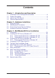
Contents Chapter 1 - Introduction and Description 1.1 1.2 1.3 1.4 Introduction to the IntelligentSerialInterface .................................. 6 Product Description ....................................................................... 6 How to Use This Manual ................................................................ 7 Technical Specifications ................................................................ 8 Chapter 2 - Hardware Installation 2.1 2.2 2.3 2.4 Safety Warnings .................
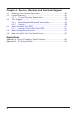
Chapter 4 - Service, Warranty and Technical Support 4.1 4.2 4.3 4.4 4.5 4.6 Software User License Agreement .............................................. 46 Limited Warranty .......................................................................... 48 4.2.1 On-line Warranty Registration......................................... 48 Tech Support ............................................................................... 49 4.3.1 Recording MultiModemISI Information ............................ 49 4.3.
Chapter 1 - Introduction and Description
ISI3334/4 Hardware/Driver Installation Manual 1.1 Introduction to the IntelligentSerialInterface The new IntelligentSerialInterface card, the MultiModemISI, is a hardware solution for adding fast serial ports to communication servers and async hosts that have 16-bit ISA-bus architecture. Serial ports are essential to communication servers, which pool modems and other communication devices for users on a LAN, and to asynchronous hosts that provide user access through serial ports.
Chapter 1 - Introduction and Description Simple to install, the MultiModemISI can be used to add multiport, Enhanced V.34 modem communications to a network host or server as easily as plugging in an expansion card, running the driver software, and connecting the phone lines. Network managers have the option of starting with the base four modem configuration (model #ISI334/4), and then adding four more modems at a later date without having to use another PC expansion slot.
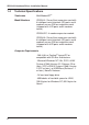
ISI3334/4 Hardware/Driver Installation Manual 1.4 Technical Specifications Tradename MultiModemISITM Model Numbers ISI3334/4--Server/Host expansion card with 8 intelligent serial interface (ISI) ports and 4 modems on one ISA-bus expansion card (shipped with 4 ISI ports and 4 modems active). ISI3334/EC--4-modem expansion module ISI3334/8--Server/Host expansion card with 8 intelligent serial interface (ISI) ports and 8 modems on one ISA-bus expansion card (shipped with 8 ISI ports and 8 modems active).
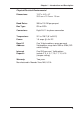
Chapter 1 - Introduction and Description Physical/Electrical/Environmental Dimensions: 13.3" x 4.8" x .6" 33.3 cm x 12.2 cm x 1.5 cm Baud Rates: 300 to 115.2K bps per port Bus Type: ISA or EISA Connectors: Eight RJ-11 for phone connection Temperature: 32° to 120°F (0° to 50°C) Power: 1.5 amps @ +5v DC Base I/O Address: One 16-byte address space per card. Valid options range from 100h to 3F0h (DIPswitch setting) Interrupt Request: One IRQ per card.
ISI3334/4 Hardware/Driver Installation Manual 10
Chapter 2 - Hardware Installation
ISI3334/4 Hardware/Driver Installation Manual 2.1 Safety Warnings 1. Never install telephone wiring during a lightning storm. 2. Never install telephone jacks in wet locations unless the jack is specifically designed for wet locations. 3. This product is to be used with UL and CUL listed computers. 4. Never touch uninsulated telephone wires or terminals unless the telephone line has been disconnected at the network interface. 5. Use caution when installing or modifying telephone lines. 6.
Chapter 2 - Hardware Installation 2.3 Determining Current System Settings When you install a device into your computer, the processor must have a means of routing information to and from the device and the device must have a means of gaining the processor's attention. These are called Input/Output (I/O) addresses and Interrupt Requests (IRQs), respectively. The MultiModemISI card requires 16 I/O addresses and one IRQ value which are not used by any other device in your system.
ISI3334/4 Hardware/Driver Installation Manual 2.4 Hardware Installation Procedure Perform the procedures in Table 2-1 to install the MultiModemISI card(s) into your PC-ISA bus computer. Installation procedures include setting the I/O address switch block and the IRQ jumper. This section may be skipped if the defaults: I/O Address 210 Hex and IRQ 10 are the values you have selected. However, if you are installing multiple cards, step 4a of Table 2-1 describes how to configure your card(s).
Chapter 2 - Hardware Installation Figure 2-1. MultiModemISI/Auxiliary Module Attachment This installation involves: i) Changing the "Modems 4 - 8" berg jumper to the 8 modem position on the MultiModemISI (see Figure 2-2). ii) Attaching both the MultiModemISI and the auxiliary module. This is accomplished by mating the pin-out connectors to the MultiModemISI to the auxiliary module; and fastening the mounting connections (four screws) of the auxiliary module to the MultiModemISI (see Figure 2-1).
ISI3334/4 Hardware/Driver Installation Manual Figure 2-2. MultiModemISI/Auxiliary Module Components Step Procedure 4a The default setting for the MultiModemISI’s base I/O address is 210 hex. The default value for the IRQ jumper is IRQ 10. Choose the IRQ value by covering the appropriate pins with the shorting plug (supplied). If your system requires a different setting or if you are installing multiple cards, refer to Appendix B for a table of valid address settings.
Chapter 2 - Hardware Installation Step Procedure 5 Install the MultiModemISI card(s) into the selected expansion slot(s) in the same manner as any other add-on card, as instructed in your computer’s documentation. 6 Fasten the retaining bracket to the computer chassis and replace the cover. 7 Your MultiModemISI card(s) requires a modular LINE JACK. This is typically an RJ11C or RJ11W jack, but could also be an RJ12 or RJ13 jack.
ISI3334/4 Hardware/Driver Installation Manual 18
Chapter 3 - MultiModemISI Driver Installation
ISI3334/4 Hardware/Driver Installation Manual 3.1 Introduction The MultiModemISI ships with a NetWare® Loadable Module (aioisix.nlm) for NetWare Connect communication Servers, and drivers for Windows® 95/NT and SCO® Open Server 5®. This chapter will guide you through the installation of these drivers. Section 3.9 details the Multi-Tech Installation Script, which is executed by a UNIX operating system.
Chapter 3 - MultiModemISI Driver Installation Table 3-1 (cont'd) Step 4 Procedure Run the Setup Utility Windows NT 3.51 Users: In the Program Manager, click on File | Run. In the command line field, type A:\setup. Follow the on-screen prompts to complete the installation of the driver. Windows NT 4.0 Users: Click on Start | Settings | Control Panel and then double click on Add/Remove Programs. The Add/Remove Programs Properties dialog box appears. Click on Install.
ISI3334/4 Hardware/Driver Installation Manual Table 3-1 (cont'd) Step 8 Procedure The Add Card dialog box appears. Configure the following parameters: Number of Ports Depending on the card you are installing, click on the correct Number of Ports. Factory Default setting is 8 Ports). I/O Base Address and IRQ The software defaults to a setting of I/O Address = 200, IRQ = 3. However, the factory default setting for all ISI Cards is I/O Address = 210 and IRQ = 10.
Chapter 3 - MultiModemISI Driver Installation 3.2.2 Removing the ISI Drivers in Windows NT 4.0 To remove the ISI drivers in Windows NT, click on Start | Settings | Control Panel and then double click on Add/Remove Programs. In the list of programs available for an uninstall, highlight ISICOM Driver and click on the Add/Remove button. Follow the on-screen prompts to complete the uninstall. Note: In order to complete an uninstall, you must reboot your system.
ISI3334/4 Hardware/Driver Installation Manual Table 3-2 (cont'd) Step Procedure 5 The ISI Card Port Count dialog box appears. Click on the number of ports you are installing, and then click on Next. 6 The Destination Directory dialog box appears. Click on Next to accept the default Destination Folder, or click on Browse to choose another location. When you are finished, click on Next to continue with the installation. 7 The Start Copying Files menu appears.
Chapter 3 - MultiModemISI Driver Installation Table 3-2 (cont'd) Step Procedure Highlight Interrupt Request and click on Change Setting. Select the proper IRQ value from the drop-down value list (choose 10 to match the default setting for the ISI card) and click OK. 13 Click on OK. 14 The following message appears (Note: although this message appears, the settings you just entered match the defaults for the ISI card.
ISI3334/4 Hardware/Driver Installation Manual Table 3-2 (cont'd) Step Procedure 17 The following message appears: Your modem has been installed successfully. Click on Finish and you are returned to the Properties menu. Note: It is recommended that at this time you change the default speed for each port from 19,200 bps to 115,200 bps to enhance performance. At this time your installation in Windows 95 is complete. 3.3.
Chapter 3 - MultiModemISI Driver Installation 3.4 Installation in SCO Open Server 5 The installation utility provided by SCO is called custom. This section is a brief guideline for invoking the utility and installing the driver. The instructions contained in the following table should only be used on SCO Open Server 5 systems. When you have completed the steps in Table 3-3, you will be directed to the Installation Script section of this chapter for a discussion of the Multi-Tech Installation Script.
ISI3334/4 Hardware/Driver Installation Manual Table 3-3 (cont'd) Step 6 Procedure At this point, your system recognizes that you are installing the Multi-Tech Serial Card Driver and prompts you to select the type of installation. Select Full Installation and press to continue. As the installation progresses, the screen displays the following messages: Extracting Files... Executing Multi-Tech Serial Card Driver Init Script...
Chapter 3 - MultiModemISI Driver Installation 3.5 The Multi-Tech Installation Script This section guides you through the Multi-Tech Installation Script for SCO and UNIXWare systems. The script requests such information as how many boards you want to install, what I/O address and IRQ values (interrupt request) you have selected and how many pseudo devices you want to create for Multi_View utility. This information extracts the necessary drivers, which will be linked with your system's kernel.
ISI3334/4 Hardware/Driver Installation Manual Table 3-4 (cont'd) Step 4 Explanation The fourth screen requests the IRQ value for this card. It is important to verify that the IRQ you select for each ISI does not overlap with existing devices or with another ISI. Type the desired IRQ value, and press . Note: if you entered a number greater than “1” at the first screen, the previous three screens reappear in sequence for each card you are installing.
Chapter 3 - MultiModemISI Driver Installation Table 3-4 (cont'd) Step 7 Explanation To change the name type N and provide a prefix of less than 5 characters. The base name you select will be used for all ports on each card you install. The following information describes the format used in naming the ISI ports: Default device name and format: ttyl ttyl BASENAME This prefix is applied to all ISI ports on all boards.
ISI3334/4 Hardware/Driver Installation Manual Table 3-4 (cont'd) Step Explanation 10 The confirmation screen lists the values you have selected. If these values are all correct, type Y and press to continue the installation process. If there is an error in any of the values displayed, type N and the first screen is re-displayed. You must then re-enter all of the information for each card. Please refer to your notes if you have multiple ISI cards to install.
Chapter 3 - MultiModemISI Driver Installation 3.6 Activating Ports in SCO Open Server 5 SCO Open Server 5 provides a device database which monitors the activity of serial ports through which users can log onto the host. If your ISI ports are used by terminals (i.e., to allow users to log onto your host), you must create an entry in the system's device database, which furnishes specific information for the terminals that will be used on each ISI port.
ISI3334/4 Hardware/Driver Installation Manual Table 3-5 (cont'd) Step Procedure 5 Repeat this process for each port on each board you have installed. Record the settings you select for each port. 6 Using the device names created in the previous section, type the following command for each port you wish to activate at this time: enable ttylbx 7 Repeat this command for each port you wish to activate, using the lower case letter for local terminal usage or upper case for modem control.
Chapter 3 - MultiModemISI Driver Installation 3.7 Multi_Setup Utility This section guides you through the Multi-Tech Setup Utility for SCO Open Server 5.0 systems. The Multi_Setup utility lets you set various parameters for Multi-Tech's ISI card ports; such as, transparent printing options, high baud settings (above 38400 bps), and hardware flow control. All the changes made by the Multi_Setup utility are in effect until the system is rebooted or until the option is changed using Multi_Setup.
ISI3334/4 Hardware/Driver Installation Manual Table 3-6 (cont’d) Command-line Options Feature -n tty Specifies the tty port. If tty is not specified, then the operation is carried on the standard input terminal. -B high/low “-B high” sets the ISI port baud rate to the high settings (see the conversion table below). “-B low” returns the ISI port to standard UNIXWare baud settings.
Chapter 3 - MultiModemISI Driver Installation 3.8 Multi_View Utility Installation This section guides you through the Multi_View Utility for SCO and UNIXWare systems. During the installation of the ISI4608 drivers, you will also install the Multi_View utility for multiple-page terminals. This section profiles the Multi_View utility and gives you the necessary information to create a Multi_View information file.
ISI3334/4 Hardware/Driver Installation Manual Once Multi_View is successfully able to read the terminal description and initialize the terminal, it comes up with a message displaying the hot-key sequence for “help”.
Chapter 3 - MultiModemISI Driver Installation 3.8.1 Description File Format A description file may contain descriptions for multiple terminal types. Each terminal entry should be separated by a blank line. The first line for each terminal contains the various names by which that terminal is known. There are three types of entries for each terminal emulation: 1) hot key entries, 2) terminal escape sequences, and 3) timing specifications. 3.8.2 Hot Key Entries These entries have three columns.
ISI3334/4 Hardware/Driver Installation Manual In other words, these entries tell Multi_View that the terminal sends the escape sequence specified in column three to Multi_View when the keystrokes specified in column two are pressed and that Multi_View should take the action specified in column one whenever it receives the characters specified in column three. 3.8.3 Terminal Escape Sequences The terminal escape sequence entries describe the escape sequence that needs to be sent to the terminal.
Chapter 3 - MultiModemISI Driver Installation A sample file for the Wyse50 terminal is provided in the following example: wy50 wyse50 vs vs sw cm cm lm qm ps ps clear time w50 Shift_F1 Shift_F2 Shift_F3 Shift_F4 Shift_F5 Shift_F6 Shift_F7 \001' \015 \001a\015 \001b\015 \001c\015 \001d\015 \001e\015 \001f\015 \033w0 \033w1 \033+ 1 ; ; ; ; ; ; ; ; ; ; ; ; line line line line line line line line line line line line 1 2 3 4 5 6 7 8 9 10 11 12 Line 1 Gives all the different names that the Wyse50 terminal
ISI3334/4 Hardware/Driver Installation Manual Each character in the escape sequence or hot key can be specified as an ASCII character if it is printable. If not printable, then it should be specified in an octal format with leading 0's, if needed, and preceded by a “\”. For example, an ASCII escape character can be specified as “\033”. Do not switch the screen while outputting as it may break the escape sequence sent to the terminal.
Chapter 3 - MultiModemISI Driver Installation 3.9 Administration Utility Multi-Tech also provides an administrative utility called "Multi_Admin" which aids in troubleshooting Multi-Tech's multiport boards. This section guides you through the Administration Utility for SCO and UNIXWare systems. This interactive menu utility displays various types of Multi-Tech's multiport boards that may be installed in your system.
ISI3334/4 Hardware/Driver Installation Manual 44
Chapter 4 - Service, Warranty and Technical Support
ISI3334/4 Hardware/Driver Installation Manual 4.1 Software User License Agreement The ISI drivers and firmware are licensed by Multi-Tech Systems, Inc. to the original end-user purchaser of the product, hereafter referred to as “Licensee.” The License includes the distribution diskette, other accompanying programs, and the documentation. The ISI drivers and firmware, hereafter referred to as “Software,” consists of the computer program files included on the original distribution diskette.
Chapter 4 - Service, Warranty and Tech Support Licensee agrees to implement sufficient security measures to protect Multi-Tech Systems’, Inc. proprietary interests and not to allow the use, copying or transfer by any means, other than in accordance with this agreement. Licensee agrees that any breach of this agreement will be damaging to Multi-Tech Systems, Inc.
ISI3334/4 Hardware/Driver Installation Manual 4.2 Limited Warranty Multi-Tech Systems, Inc. (“MTS”) warrants that its products will be free from defects in material or workmanship for a period of ten years from the date of purchase, or if proof of purchase is not provided, ten years from date of shipment. MTS MAKES NO OTHER WARRANTY, EXPRESSED OR IMPLIED, AND ALL IMPLIED WARRANTIES OF MERCHANTABILITY AND FITNESS FOR A PARTICULAR PURPOSE ARE HEREBY DISCLAIMED.
Chapter 4 - Service, Warranty and Tech Support 4.3 Tech Support Multi-Tech has an excellent staff of technical support personnel available to help you get the most out of your Multi-Tech product. If you have any questions about the operation of this unit(s), call 1800-972-2439. Please fill out the information (below), and have it available when you call. If you require service, the tech support specialist will advise you in Multi-Tech's service procedure (Section 4.3.2). 4.3.
ISI3334/4 Hardware/Driver Installation Manual 4.3.2 Service If your tech support specialist decides that service is required, your unit may be sent (freight prepaid) to our factory. Return shipping charges will be paid by Multi-Tech Systems (within North America). Include the following with this product: • a description of the problem. • return billing and return shipping addresses. • contact name and phone number. • check or purchase order number for payment if the MultiModemISI is out of warranty.
Chapter 4 - Service, Warranty and Tech Support 4.4 About the Multi-Tech BBS Multi-Tech Systems maintains a Bulletin Board Service (BBS) for its customers. The information available via the BBS includes: new product information, product upgrade data, problem solving tips, and a message service for you to leave questions for which you would like additional information. The phone number for the Multi-Tech BBS is (612) 785-3702 or (800) 392-2432 (U.S.A. and Canada).
ISI3334/4 Hardware/Driver Installation Manual 6. At the Message Menu, you can leave a message to the Sysop (you can not read messages at this point). The BBS will tell you if you have a personal message (mail). At the prompt (would you like to read it now?), type R for read now. You must read your message(s) when you first access the BBS. 4.5 About CompuServe/Internet In addition to the BBS, Multi-Tech provides support through CompuServe's Modem Vendor Forum (GOMODEMVEN) under GO MULTITECH.
Chapter 4 - Service, Warranty and Tech Support 4.6 About the Multi-Tech Fax-Back Service Multi-Tech's fax-back system provides 24-hour access to sales, marketing, and technical literature. Dial 612-717-5888, follow the voice prompts, and request document number 10 for a catalog of available documents. For convenience, have your fax number handy:________________ . From the catalog of available documents, you can order newsletters, white papers, press releases, etc.
ISI3334/4 Hardware/Driver Installation Manual 54
Appendixes
ISI3334/4 Hardware/Driver Installation Manual Appendix A - Base I/O Address Switch Settings The table below provides the DIP-Switch settings for valid base I/O addresses of the ISI4608. The switches can be set to "OPEN" (O in the table below) or to "CLOSED" (C in the table below). Holding the board with the switch facing you (reading numbers 1-8 left to right), the "UP" position for the switch is OPEN, and the "DOWN" position is CLOSED.
Appendix A - Base I/O Address Switch Settings Table A-1 (cont'd) (hex) 1D0 1D8 1E0 1E8 1F0 1F8 *200 S1 C O C O C O C S2 O O C C O O C S3 C C O O O O C S4 O O O O O O C S5 O O O O O O C S6 O O O O O O C S7 C C C C C C O S8 C C C C C C C 208 210 218 220 228 230 238 240 248 250 258 260 268 270 278 280 288 290 298 2A0 2A8 2B0 2B8 2C0 2C8 2D0 O C O C O C O C O C O C O C O C O C O C O C O C O C C O O C C O O C C O O C C O O C C O O C C O O C C O C C C O O O O C C C C O O O O C C C C O O O O C C C C
ISI3334/4 Hardware/Driver Installation Manual Table A-1 (cont'd) (hex) 2D8 2E0 2E8 2F0 2F8 300 308 310 318 320 328 330 338 340 348 350 358 360 368 370 378 380 388 390 398 3A0 3A8 3B0 3B8 3C0 3C8 3D0 3D8 3E0 3E8 3F0 3F8 58 S1 O C O C O C O C O C O C O C O C O C O C O C O C O C O C O C O C O C O C O S2 O C C O O C C O O C C O O C C O O C C O O C C O O C C O O C C O O C C O O S3 C O O O O C C C C O O O O C C C C O O O O C C C C O O O O C C C C O O O O S4 O O O O O C C C C C C C C O O O O O O O O C C C C
Appendix B - ISI Testing Utilities Appendix B - ISI Testing Utilities This disk contains two files that are to be used in conjunction with ISI boards. These files are described in two sections: 1) Operation with factory default settings, and 2) Operation with other than the factory default settings. These files are: ISI3334.BIN 3334TERM.EXE Note: This program is a DOS utility. 1. OPERATION WITH FACTORY DEFAULT SETTINGS The 3334TERM.
ISI3334/4 Hardware/Driver Installation Manual The first step in this utility is to identify the port to be tested. In order for the test to function, the selected port must be connected to an activated modem. The valid entries for the ISI are 1 through 8.
Appendix B - ISI Testing Utilities Whenever the Base IO Address and/or the IRQ values have been changed, a parameter string must be added to the command line. The string takes the form of [-Axxxx], where xxxx represents the new Base IO Address value and [-Iy], where y represents the IRQ value selected.
ISI3334/4 Hardware/Driver Installation Manual The first step in this utility is to identify the port to be tested. In order for the test to function, the selected port must be connected to a modem that is switched on. The valid entries for the ISI are 1 through 8.