Model MTA128ST
Owner's Manual P/N 82072600 Revision A Models MT128ISA-SD MT128ISA-SV MT128ISA-UD MT128ISA-UV Copyright© 1998 by Multi-Tech Systems, Inc. All rights reserved. This publication may not be reproduced, in whole or in part, without prior written permission from Multi-Tech Systems, Inc. Multi-Tech Systems, Inc. makes no representations or warranties with respect to the contents hereof and specifically disclaims any implied warranties of merchantability or fitness for any particular purpose.
EMC, Safety, and Terminal Directive Compliance The CE mark is affixed to this Multi-Tech product to confirm compliance with the following European Community Directives: Council Directive 89/336/EEC of 3 May 1989 on the approximation of the laws of Member States relating to electromagnetic compatibility; and Council Directive 73/23/EEC of 19 February 1973 on the harmonization of the laws of Member States relating to electrical equipment designed for use within certain voltage limits; and Council Directive 91
Contents Contents Chapter 1 - Introduction .................................................................. 7 1.1.1 Product Description .............................................................. 7 ......................................................................................................................... .................................................................................................................. .......................................................................
Contents 13 2.3 Environment Setup ........................................................................... 13 ......................................................................................................... 13 2.3.1 Terminator Setup ................................................................ 13 2.4 Installation .......................................................................................... 16 2.4.1 Windows 3.1 Installation and Driver Configuration ......... 16 2.
Contents 6-IWay Hopper
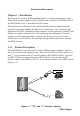
Introduction/Description Chapter 1 - Introduction Welcome to the world of ISDN communications. You have acquired one of the finest ISDN terminal adapters (TAs) available today, model(s) MT128ISA-SD/SV and MT128ISA-UD/UV from Multi-Tech Systems. The proliferation of PCs and LANs with bandwidth-intensive applications has generated a powerful demand for high-speed connections.
Introduction/Description Your internal ISDN PC card is compatible with prevalent ISDN switch protocols. It communicates using ISDN BRI (2B+D) service, which provides up to 128K bps data communications.
Introduction/Description 1.2.1 What Is in Your ISDN PC Card Package? Before installating your terminal adapter, check the package contents. Your package should include: one internal ISDN PC adapter Installation Disk(s) for Windows 3.1, Windows 95, and Windows NT RJ-45 cable (6 ft.
Introduction/Description Appendices Appendix A Appendix B 1.3 - Application Program Interfaces (APIs) - EC Type and FCC Regulations Technical Specifications Model Number(s) MT128ISA-SD, MT128ISA-SV and MT128ISA-UD, MT128ISA-UV Network Interface RJ-45 S/T Interface or RJ-45 U Interface POTS Interface (V models) Switch Compatibility AT&T 5ESS, Nortel DMS-100, US NI-1 & NI2, ETSI, INS-64 B-Channel Protocols Voice, Data (56K, 64K, 112K or 128K HDLC), V.120, X.75, Async. PPP to Sync.
Installation Chapter 2 - Introduction This chapter describes how to make all the physical and software driver connections nescessary in order for your terminal adapter to operate in an ISDN environment. Before installing your terminal adapter, check the package contents (see section 1.2.1 in Chapter 1 for package contents list).
Installation in their ISDN BRI network and an end-user's four wire terminal equipment. The NT1 drives an S/T-bus which is usually 4 wires, but in some cases may be 6 or 8 wires. The name of the S/T bus comes from the letters used in the ISDN specifications to refer to two reference points, S and T. Point T refers to the connection between the NT1 device and customer supplied equipment. Terminals can connect directly to NT1 at point T, or there may be a PBX (private branch exchange, i.e.
Installation 2.2.4 Safety Warnings 4 Never install telephone wiring during a lightning storm. 4 Never install a telephone jack in a wet location unless the jack is specifically designed for wet locations. 4 Never touch uninsulated telephone wires or terminals unless the telephone line has been disconnected at the network interface. 4 Use caution when installing or modifying telephone lines. 4 Avoid using a telephone (other than a cordless type) during an electrical storm.
Installation RJ11/Analog Connection RJ45/ISDN Connection JP1 JP2 MT128ISA-Data/Voice Figure 2-2 Internal ISDN PC Card Illustration 2a. Turn off your computer power and remove the PC cover. 2b. Insert the ISDN adapter into a open PC ISA slot and secure it. 2c. Replace the PC cover. 3. Make the analog device connection (V models only). MT128ISA-SV and MT128ISA-UV provide a POTS interface with RJ-11 jack to connect with current analog devices.
Installation PHONE RJ11 Analog Connection (telephone, G3 Fax, Answering Machine, Modem or PBX Trunk) RJ45 BRI Connection LINE LINE OUT MIC IN Figure 2-3 Modular Analog and BRI Connections 4a. Make the ISDN connection. Connect the MT128ISA-SD/SV adapter and NT1 with RJ-45 cable connector, and insert the ISDN BRI line into the correct NT1 socket. OR 4b Insert the ISDN BRI line with the RJ-45 connector cable directly into the RJ45 jack on the MT128ISA-UD/UV adapter.
Installation 2.4 Installation After you setup your ISDN environment, turn your computer power ON and start the driver installation. Your ISDN adapters support Microsoft Windows environments; read the appropriate installation section for your PC system. 2.4.1 Windows 3.1 Installation and Driver Configuration You can configure your ISDN connection via COM port emulation, standard WinISDN interface, or standard the CAPI 2.0 interface in Windows 3.1. Follow these steps: 1.
Installation 3a. ISDN Switch Type. Choose the country name for your location, or select an appropriate ISDN switch type in your country (especially for U.S. customers). 3b. Codec. Countries adhering to the European telecommunication standard may choose A-Law. Countries adhering to the U.S. telecommunication standard may choose u-law. 3c. Standby Time. This is a timer which buffers any keypads input from an analog device before sending a message out. Do not change the default value. 3d. MSN (POTS).
Installation The ISDN LOG application is used to record the handshaking and data transfer process during communication. It can be used for debugging purposes so it is useful to have the log running while first starting to use the ISDN system. The Line Diagnostic is used for on-line channel testing between the ISDN switch and subscriber site, and getting ISDN line status. Please refer to Chapter 4 for detailed information. 5.
Installation 2. WinISDN Interface. The ISDN driver can transmit/receive data with applications through the standard WinISDN interface. The following TCP/IP stacks support the WinISDN interface. NetManages Chameleon FTPs Explore Frontiers SuperHighway Access Refer to the proper TCP/IP stack document respective to your setup dial-up environment for WAN and LAN. We recommend NetManages Internet Chameleon (version 4.5 or later) for compatibility using both PPP and Multilink PPP. 3. CAPI Interface.
Installation Figure 2-6. ISDN Adapter Properties Configuration in Windows 95 is similar to the installation in a Windows 3.1 environment. The MSN (POTS) value is only relevant to V models and determines which telephone number to associate with the POTS interface (e.g., if the number 341317 was entered then a normal telephone attached to the POTS interface would ring on a call coming in to the number 341317). For the UK and most European countries, the EURO ISDN switch type with A-law Codec is selected.
Installation 4. If you already installed the ISDN Accelerator Pack 1.1 (MSISDN11.EXE), then go to the next setup section. To update the Dial-Up Networking to support 2B channel (MLP) connection and NDISWAN Miniport interface you will need to install the Win95 MSISDN11.EXE (version 1.1 or above) upgrade pack. You can get the file from our Windows 95 installation diskette and it is also accessible from Microsofts web site. Run the MSISDN11.EXE program and follow the installation instructions. 5.
Installation Figure 2-7. NDISWAN Miniport Adapter Installation 2. Win95 will now indicate that it has found one compatible device.
Installation Figure 2-8. Binding the NDISWAN Protocol 2b. Click OK. You will see an ISDN Configuration window display-- Because you have installed our ISDN NDISWAN driver, the ISDN Accelerator Pack requests some information about your ISDN service. Click Next.
Installation Figure 2-9. ISDN Configuration Window 2c. Select Automatic for the Switch protocol and click Next. 2d. Leave the Phone number and SPID fields blank. Click Next»Finish, and reboot the system. 3. Configure Dial-Up Networking to access the Internet. Now when you use the dial-up networking to create a new connection (Start»Programs»Accessories»Dial-Up Networking»Make New Connection), you can select the first device of IINWan95 in the connect using field.
Installation Figure 2-10. Dial-Up Networking Setup through NDISWAN-1 4. Enter the ISP or remote LAN phone number you wish to connect. Click Next»Finish. You will see a new connection icon (NDISWAN) added into Dial-Up Networking folder. Choose the new connection icon, click the right mouse button, choose Properties.
Installation Figure 2-11. Dial-Up Networking Setup through NDISWAN-2 5. If you want to use 128K MLP (check if your ISP supports this feature) connection, you need choose another IINWan95 device. In Figure 2-12, Settings»Use»additional device»Add»select the second IINWan95 device (IINWan95-Line02 in this case).
Installation Figure 2-12. NDISWAN 128 MLP Setup Ensure that you choose the correct ISP settings such as Server Type and TCP/IP values. Contact your ISP or refer to Figure 2-13 as an example. You are now ready to make a connection to your ISP and access the Internet through the NDISWAN Miniport adapter.
Installation Figure 2-13. Server Types and TCP/IP Settings Example 2.6.1 Connection Through the Virtual Modem After installing Win95 drivers, two virtual ISDN COM ports are automatically created. You must check the virtual COM port value, add the modem (virtual) connection with the ISDN COM port, and check the virtual modem parameters value. Refer to Chapter 3 for AT Command descriptions. 1. Check the Virtual COM Port value.
Installation Recommended values are: Bits per second: 115200 Data bits: 8 Parity: None Stop bits: 1 Flow control: None FIFO control: None (fill at Advanced tab) 2. Select the Start»Settings»Control Panel»System»Device Manager»Ports (COM & LPT), ISDN ComPort1»ISDN Comport2, Properties»Port Settings to check the ISDN COM1 / ISDN COM2 port parameters. Figure 2-14.
Installation 3. Adding Virtual Modems connecting with two ISDN COM ports. You can add a virtual modem with ISDN proprietary virtual modem. For installation convenience, your ISDN driver provides several proprietary virtual modems in Windows 95. Select Start Settings»Control panel»Modems»Add»Select do not detect my modem, I will select it from a list, Next . 4. Click Have Disk, and browse to the MODEM sub-directory on the Windows 95 installation diskette (e.g., A:\MODEM). Select the mdmasu.inf file.
Installation Figure 2-16. Linking Virtual Modem to Com Port The ISDN modems are used for the following purposes: The Async to Sync PPP modem is used for 64K Internet Access. X.75 Transparent modem is used for BBS access and file transfer. The Universal-1 and -2 are multi-purpose modems. In Universal modem mode, the ISDN driver selects HDLC as the default, but you can change to the appropriate protocol through the ATBn commands (see Chapter 3).
Installation Figure 2-17. ISDN Modem Parameter Configuration 2.6.2 Configure the Dial-Up Network for Internet Access Refer to the examples of 64K and 128K Internet connection with Dial-Up Networking through the ISDN virtual modem. 64K Access 1. You can make a new connection by: Selecting Start»Programs»Accessories»Dial-Up Networking»Make New Connection. Select the ISDN (Async to Sync PPP, 64K) Adapter modem, click Configure tab, make sure the modem connection is to the ISDN ComPort1 or ComPort2. 2.
Installation 3. Make a connection to your ISP and access the Internet through the virtual modem interface (64K connection). Figure 2-18. Choose ISDN Adapter Properties 128K/MLP Access 1. If you want to make a connection with 128Kbps, confirm that your ISP supports 128K MLP - some dont or if they do are often allowed at an extra cost. Make sure you have installed the Microsofts ISDN Accelerator Pack (MSISDN11.EXE). Next go to Dial-Up Networking to Make New Connection. 2.
Installation Figure 2-19. Choose Universal Modem-1 3. Use Configure»Connection»Advanced»Extra Settings to add the ATB41 command. Click OK, OK.
Installation Figure 2-20. Choose Universal Modem-1 with Additional Settings 4. Click on Next, on the next dialog box enter the area code and phone number to use for first connection channel with your ISP.
Installation Figure 2-21. Make A Dial-Up Connection 5. Click on Next, and click on Finish. A new connection icon is added to the Dial-Up Networking group. Click on right mouse button over the new connection icon to access Properties. 6. On the Properties»General screen for the new connection, make sure that Primary Device is set to the Universal-1 Modem related to the first ISDN COM port. 7. On the Properties»General screen, click the Settings tab and select the Use additional device option.
Installation Figure 2-22. Choose additional device for 128K Connection 8. Go to the Properties»Server Type screen and select PPP: Windows 95, Windows NT 3.5, Internet for the Type of Dial-Up Service. Under TCP/IP Setting, enter the user IP Address and the DNS address for your ISP. Setup for a 128K (MLP) connection through the virtual modem is complete. You can double click on the connect icon or click on the right mouse button and select the Connect menu item. The Connect To dialog box is displayed.
Installation connection dialog just under the first channel connection asking for a user name and password. This can be disabled for future connections by entering your user name ID and password again on this second screen. 2.6.3 Removing ISDN Drivers for Windows 95 To remove ISDNdrivers from Windows 95: 1. Remove the NDISWAN adapter (NDISWAN driver), do not reboot Windows after removing adapter. Select Start»Settings»Control Panel»Network, choose IINWan95 - ISDN Adapter, »Remove. 2.
Installation Figure 2-23. Network Icon for Windows NT 2. Click add.
Installation Figure 2-24. Select Network Adapter for Windows NT Installation 3. Click Have Disk tab and specify the Drive and Directory of ISDN NT driver. 4. Select ISDN PC Adapter, click OK. 5. You will see the ISDN Driver Bus Location dialog box, select ISA as the Bus Type, and the Bus Number to 0, then click OK.
Installation Figure 2-25. Select Bus Type for Windows NT Installation 6. Windows NT copies the ISDN driver into system. 7. We provide the IRQ and I/O manual configuration (Figure 2-26), but suggest use of our Auto configuration utility. In the ISDN Configuration dialog box, you can fill the calling party number and calling party subaddress from NDISWAN Setting tab.
Installation Figure 2-26. ISDN Configuration for Windows NT Installation 8. Click OK to continue. 9. If you change any value in the ISDN configuration dialog box, you will bewarned that you will need to restart the Windows NT for the settings to take effect. 10. Click OK to install and setup RAS. Figure 2-27.
Installation 11. If you have installed the RAS, please refer next step to install ISDN ports for RAS. If not, please install the RAS now. Please refer Figure 2-28 , click the services tab to add RAS. The RAS is provided by Microsoft, you need to prepare the Installation disks or CD of Windows NT to continually install it. You should jump to next step when RAS installer asks to add port device. 12. You will get a window like below.
Installation Figure 2-29. Configure Port Usage Installation 14. If you choose Dial out only, click OK, and then click the Network tab, and check which protocol you want. If you are going to access Internet, choose TCP/IP. Figure 2-30. Configure Dial Out Protocol 15. If you choose Receive calls, or Dial out and Receive calls, click OK and then click the Network tab, you will get a window like below. Please check your ISP or network administrator for TCP/IP settings (see Appendix B for assistance).
Installation Figure 2-31. Configure Network Configuration 16. Select the ISDN2 and do the same things as above, then click Continue tab. 17. At this stage, you have installed the ISDN drivers in your Windows NT successfully, then click Close tab. 18. You need to restart your computer now. 2.6.5 Configuring an Access Account over ISDN Now, you need to configure an access account over ISDN in Dial-Up Networking. 1. Select Start»Programs»Accessories»Dial-Up Networking.
Installation details for your ISP. Click Next > and select IINWANNT and click Next >. Enter the phone number of ISP and click Next. Click Finish. You will get a window like below. Figure 2-32. Configure Dial-Up Networking 2. To configure server settings or dialing properties, click on the More button and select the item you want to change from the pull down list. Click Dial to make a connection with server over ISDN.
Installation c. Click Configure and check the check boxes for IINWANNT(ISDN1) and IINWANNT(ISDN2). d. Select IINWANNT(ISDN1), click Phone numbers, enter the first phone number, click Add, and click OK. e. Select IINWANNT(ISDN2), click Phone numbers, enter the first phone number, click Add, and click OK. f. You are now ready to make 2B connection with server. Make sure that your ISP or remote server does in fact support 128K MLP and also that it has been enabled for you by the remote server.
Installation 2.6.6 Accessing the Outside World Using Dial-Up Networking You are now done with the configuration process and should be ready to make a connection to your server. Click the Dial-Up Networking icon, and select the name configured above in the phone book entry and click Dial. The system should then dial and connect to your ISP at either 128k or 64k depending on how you setup the call. The server will verify your login name, password, and register you on the server.
Installation 2.6.8 Removing ISDN Driver for Windows NT Click the Network Icon in the Control-Panel and Adapters tab. Choose MultiTechs ISDN Driver, then click Remove. Figure 2-34.
AT Commands/S-Registers 50-IWay Hopper
AT Commands/S-Registers 51-IWay Hopper
AT Commands/S-Registers 52-IWay Hopper
AT Commands/S-Registers 53-IWay Hopper
AT Commands/S-Registers 54-IWay Hopper
AT Commands/S-Registers 55-IWay Hopper
AT Commands/S-Registers 56-IWay Hopper
AT Commands/S-Registers 57-IWay Hopper
AT Commands/S-Registers 58-IWay Hopper
AT Commands/S-Registers 59-IWay Hopper
AT Commands/S-Registers 60-IWay Hopper
AT Commands/S-Registers 61-IWay Hopper
AT Commands/S-Registers 62-IWay Hopper
AT Commands/S-Registers 63-IWay Hopper
AT Commands/S-Registers 64-IWay Hopper
Troubleshooting 65-IWay Hopper
Troubleshooting 66-IWay Hopper
Troubleshooting 67-IWay Hopper
Troubleshooting 68-IWay Hopper
Troubleshooting 69-IWay Hopper
Troubleshooting 70-IWay Hopper
Troubleshooting 71-IWay Hopper
Service 72-IWay Hopper
Service 73-Iway Hopper
Service 74-IWay Hopper
Service 75-Iway Hopper
Service 76-IWay Hopper
Service 77-Iway Hopper
Configuration Profiles 78-IWay Hopper
Configuration Profiles 79-IWay Hopper
Configuration Profiles 80-IWay Hopper
Configuration Profiles 81-IWay Hopper
Configuration Profiles 82-IWay Hopper
Configuration Profiles 83-IWay Hopper
Product Update 84-IWay Hopper
Product Update 85-IWay Hopper
Product Update 86-IWay Hopper
Product Update 87-IWay Hopper
Product Update 88-IWay Hopper
Product Update 89-IWay Hopper
Product Update 90-IWay Hopper
Product Update 91-IWay Hopper
Product Update 92-IWay Hopper
Product Update 93-IWay Hopper
Product Update 94-IWay Hopper
Product Update 95-IWay Hopper
Product Update 96-IWay Hopper
Product Update 97-IWay Hopper
Product Update 98-IWay Hopper
Product Update 99-IWay Hopper
Product Update 100-IWay Hopper
Product Update 101-IWay Hopper
Product Update 102-IWay Hopper
Product Update 103-IWay Hopper
Product Update 104-IWay Hopper
Product Update 105-IWay Hopper
Product Update 106-IWay Hopper
Index Index Symbols 128K Connection 37 128K/MLP Access 33 64K Access 32 A Adapter Properties 20, 33 Application Interface Setup 18 Application Interfaces 10 B B-Channel Protocols 10 Binding the NDISWAN Protocol 23 BRI Connections 15 C Choose Adapter Properties 33 Choose Universal Modem-1 34 Choose Universal Modem-1 with Additional Settings 35 Com Port 31 Compatibility, switch 10 ComPort Configuration 29 Configuration for Windows NT Installation 42 Configure Dial Out Protocol 44 Configure Network Configu
Index Dial-Up Connection 36 Dial-Up Networking 46, 48 Dial-Up Networking Setup through NDISWAN-1 25 Dial-Up Networking Setup through NDISWAN-2 26 Driver Configuration 16 Drivers for Windows 95 38 E Environment Setup 13 F Features 8 G Group Folder 17 H Hardware 10 I Installation 1149, 16 Internet Access 12, 32 Introduction 7 ISDN BRI Line 11 ISDN Configuration Display 16 ISDN Configuration Window 24 ISDN Group Folder 17 ISDN Interface Points 7, 12, 14, 15, 16, 17, 20, 22, 23, 24, 25, 26, 27, 28, 29, 30
Index M Make A Dial-Up Connection 36 Manual Organization 9 Manual organization 9 Model Number(s) 10 Modem Parameter Configuration 32 Modular Analog and BRI Connections 15 Modular Analog Connections 15 Multiple Line Configuration 47 N NDISWAN 128 MLP Setup 27 NDISWAN and Virtual Modem Interface Connections 21 NDISWAN Interface Connections 21 NDISWAN Miniport Adapter Installation 22 Network Adapter for Windows NT 40 Network Interface 10 NT1 Connection 11 P Product Description 7 R RAS 42 Reconfigure the IS
Index ST and U Interface Options 7 Supported Applications 10 Switch Compatibility 10 T Terminator Setup 13 V Virtual Modem 28, 31 Virtual Modem Installation 30 Virtual Modem Interface Connections 21 Voice coding 10 Voice Coding 10 W Warranty 10 What Is in Your ISDN PC Card Package 9 What Is in Your ISDN PC Card Package? 9 What Is in Your Modem Package? 9, 11 Windows 3.
Index 111-IWay Hopper
Index 112-IWay Hopper
Index 113-IWay Hopper
Index 114-IWay Hopper
Index 115-IWay Hopper
Index 116-IWay Hopper
Index 117-IWay Hopper