Server Farm Model MA3a User Guide
User Guide 88311200, Revision A MultiArrayIII (Model # MA3a) User Configurable Multiple-processor Rack Mount Chassis This publication may not be reproduced, in whole or in part, without prior expressed written permission from Multi-Tech Systems, Inc. All rights reserved. Copyright © 1998, by Multi-Tech Systems, Inc. Multi-Tech Systems, Inc.
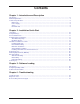
Contents Chapter 1 - Introduction and Description Introduction ................................................................................................................................................ Manual Organization .................................................................................................................................. Technical Specifications .............................................................................................................................
Chapter 5 - Warranty, Service and Technical Support Introduction .............................................................................................................................................. Limited Warranty ...................................................................................................................................... On-line Warranty Registration ............................................................................................................
Chapter 1 - Introduction and Description
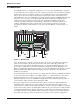
MultiArray User Guide Introduction The MultiArrayIII™ user-configurable multiple-processor server farm (model MA3a) is designed to consolidate up to nine network servers into a single system that can be mounted in a standard 19-inch rack enclosure. The MA3a contains a user-configurable 20-slot segmented backplane that sits on the floor of the chassis. On the upper left front of the chassis sits an 8-bay, 3½" vertical disk drive chassis.
Chapter 1 - Introduction and Description Manual Organization This manual tells you how to install your MultiArray hardware. For information on the Multi-Tech or third party PentiumTM Based Single Board Computer (SBC), Network Interface Card (NIC), Intelligent Serial Interface (ISI) Boards, etc., refer to the user documentation shipped with the board. For information on running software on the MultiArray, refer to the applicable software user documentation, shipped with your software package.
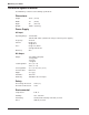
MultiArray User Guide Technical Specifications The MultiArrayIII conforms to the following specifications: Dimensions Height: 10.75" (27 cm) Width: 19" (48 cm) Depth: 25" (63.5 cm) Weight: 100 lbs. (45.35 kg) Power Supply AC Input Operating Range: 115-230 VAC 180-270 VAC switch (switch must change on all four power supplies) Frequency: 47-63 Hz Current: 6A @ 115V 3A @ 230 V Fuse: 5A @ 115V, 60 Hz 2.
Chapter 2 - Installation Quick Start
MultiArray User Guide Unpacking Check the items on the MultiArray shipping list to ensure that you have received the correct accessories. Your MultiArray should include: • • • • • • • MA3a chassis (with included CD-ROM and floppy drives) Two AC power cords Accessory kit (with jumper cards and ribbon cables) Driver diskette This Quick Start Guide User Guide diskette Tucows® accessory CD Unpack and inspect the MultiArray rack for visible shipping damage.
Chapter 2 - Installation Quick Start Pre-Installation Notes Due to the high flexibility of the MultiArray, the options for configuration are many and varied. You may be installing Multi-Tech components throughout, or combining components from other vendors. For this reason this quick start guide, and these installation instructions, are written in such a way as to be relevant to all possibilities.
MultiArray User Guide 9-Pin DSUB Openings If the 9-pin DSUB openings will be used on the upper back panel of the MA3a chassis, the coverplates need to be removed. Use a screwdriver (or similar tool) to punch the metal insert out from the inside. The 9-pin connector can then be bolted to the chassis. Figure 2-1 shows the 9pin openings on the back panel of the MA3a. 9-Pin DSUB Openings Figure 2-1.
Chapter 2 - Installation Quick Start Backplane Board The user configurable backplane shown in Figure 2-2 allows you to combine subsegments (2card slots, i.e., SUB 1 NIC and CPU with SUB2 NIC and CPU) into a 4-slot segment. The first two segments can be combined into a 6-slot segment along with the second and remaining three segments being combined into 4-slot segments. Combining the first two segments is accomplished by inserting a bus jumper circuit board (see Figure 2-3) into connector P5.
MultiArray User Guide Hardware Installation Procedure Depending on the individual configuration, the installation procedure may involve installing SBC boards, NICs, ISI boards, hard disk drives, and tape drives into your MultiArray rack, cabling, and mounting the rack in a standard 19-inch rack enclosure. Perform the following procedures to install your MultiArray. WARNING: Anytime power has to be removed from the complete rack, turn off the Master Power switches inside the front door.
Chapter 2 - Installation Quick Start Note: Installing SBCs in a 4-slot segment requires an SBC to the left of the bus jumper. Installing SBC Boards 1 Verify SBC board configuration; refer to the hardware configuration and installation section in the SBC user documentation. 2 Remove the slot cover plate on an open slot marked “CPU,” depending on how the backplane is configured, and retain the cover plate mounting screw.
MultiArray User Guide Internal SBC Cabling The internal cabling process involves the connection of each individual SBC to the mux card in the MA3a chassis. The mux board connectors are shown in Figure 2-5. SFDD8 SFDD9 SFDD7 SHDD8 SFDD6 SHDD6 SHDD9 SHDD7 SFDD5 SFDD4 SFDD3 SHDD5 SHDD4 SFDD2 SHDD2 SFDD1 SHDD1 CD-ROM Drive Floppy Drive SHDD3 Power for CD-ROM and Floppy Drives HDD7 HDD9 HDD8 HDD6 HDD5 HDD4 HDD3 HDD2 HDD1 Figure 2-5.
Chapter 2 - Installation Quick Start SBC Connections Figure 2-6 shows the two connections between the mux card and the SBC. Floppy Drive Connector Pin 1 34-pin Ribbon Cable (15) SBC OPEN 1 2 3 4 5 6 7 8 SOCKET 7 Hard Drive Connector LOCK 40-pin Ribbon Cable (13) BANK 2 M1 Hard Drive Connector M2 M3 M4 Floppy Drive Connector BANK 1 Pin 1 Mux Card Figure 2-6.
MultiArray User Guide Disk Drive Installation Installing Drives in the 8-Bay Disk Drive Chassis 1 Open the front door on the rack. Note: Although you can remove the front door for installation purposes, you must replace the door prior to applying power to the unit. 2 Remove the two top front drive chassis mounting screws. See Figure 2-7. 3 Loosen, but do not remove, the two rear drive chassis mounting screws. See Figure 2-7.
Chapter 2 - Installation Quick Start 7 Select the slot to install the disk drive and slide it into the slot. See Figure 2-8. Drive Mounting Screws (4 per device) Chassis Mounting Screws (4) 8-Bay Vertical Drive Chassis Disk Drives (Hard or Floppy Drives) Figure 2-8. Disk Drive Installation 8 Align the disk drive with the mounting holes in the top of the chassis and secure the drive to the chassis with the four mounting screws provided with the drive.
MultiArray User Guide 8-Bay Disk Drive Cabling The disk drive cabling process involves making the connections between each disk drive and the mux card via the ribbon (data) cables, and between each drive and the power connectors on the backplane via the Y cables. The mux board connectors are shown in Figure 2-9.
Chapter 2 - Installation Quick Start 2 If the drive has an IDE interface, connect the other end of the ribbon cable to its associated Mux connector, insuring that pin 1 of the cable mates with pin 1 of the Mux connector. See Figure 2-10. 3 Connect the power cable associated with the SBC to the disk drive ensuring that pin 1 of the cable mates with pin 1 of the drive connector. The power cables are a Y-cable with a small connector for a floppy disk drive and a large connector for a hard disk drive.
MultiArray User Guide Installing a Disk Drive into Horizontal Chassis Your MA3a comes pre-configured with a floppy and CD-ROM drive installed in the combination horizontal drive chassis. The data and power cables from these drives have already been connected. If you wish to add a disk drive, proceed with the following procedure. 1 Remove the two top front combination horizontal chassis mounting screws. See Figure 2-12. 2 Loosen, but do not remove, the two top rear chassis mounting screws.
Chapter 2 - Installation Quick Start 6 To mount a half height drive in the combination horizontal chassis, the drive has to first be attached to the half height disk drive mounting bracket. To mount the drive to the bracket, place the drive in the bracket and secure it to the four side tabs or the four bottom tabs on the bracket. Use the four mounting screws supplied with the drive.
MultiArray User Guide 11 Connect the power cable to the disk drive ensuring that pin 1 of the cable mates with pin 1 of the drive connector. The power cables are a Y-cable with a small connector for a floppy disk drive and large connector for a hard disk drive. See Figure 2-15.
Chapter 2 - Installation Quick Start 13 Reconnect the power cables to the floppy and CD-ROM drives. See Figure 2-17. Mux Card Floppy Disk Drive CD-ROM Drive Figure 2-17. Floppy and CD-ROM Drive Power Connections 13 Slide the chassis all the way into the MultiArray and tighten the back two mounting screws and replace the two front mounting screws. Replacing Cover Align the holes in the cover with the retaining screws on the MA3a chassis. Replace the top cover and slide towards the front of the chassis.
MultiArray User Guide External Cabling The descriptions below are appropriate for Multi-Tech products. For other vendor components, refer to the user documentation for that component. Note 1: Prior to making the external connections, make sure that the chassis cover has been replaced and all retaining screws tightened. Note 2: If you are using the MultiArray in tandem with the Multi-Tech Video/Keyboard/Mouse Switch (model MS9E), refer to the MS9E Owner’s Manual for additional cabling instructions.
Chapter 2 - Installation Quick Start Powering Up Before powering-on the MultiArray verify the following information: • Verify that both power cords are attached to the unit and to a live AC outlet. Both of the power cords must be plugged in for the system to operate properly. • Verify that the slide switch on all four power modules is set for the appropriate AC voltage (either 115V or 230V). • Verify that the power switch for each of the four power modules is on before master power switches are turned on.
MultiArray User Guide 28
Chapter 3 - Software Loading
MultiArray User Guide Introduction This chapter discusses software options available on the MultiArray. The hardware installation procedures in Chapter 2 of this manual must be performed before starting any software loading or operating procedures. Configuring Multiple SBCs When configuring multiple SBCs from a single floppy disk drive, ensure that the diskette is writeprotected or remove the diskette from the disk drive before toggling the BCD display to another segment.
Chapter 4 - Troubleshooting
MultiArray User Guide Troubleshooting The recommended troubleshooting process for the MultiArray is to determine the following results: • Is the rack plugged in and does the wall plug have power. • If power supply ALARM sounds: 1) Check to see if power supply LEDs are ON and fans are running. 2) If power supply LED is OFF, check that power supply is turned on. 3) If power supply LED is OFF and fans are not running, turn power supply module off for at least 10 minutes. Then, turn back on.
Chapter 4 - Troubleshooting Diagnostic Tests The SBC operates much like any stand-alone PC, and the MultiArray will run almost any diskettebased off-the-shelf diagnostic program. These programs are available at any software re-seller, and can quickly help isolate component failures. Before Calling Technical Support For immediate help in finding and fixing MultiArrayIII problems, record the error condition and call Multi-Tech’s Technical Support Department (refer to Chapter 5 of this manual).
MultiArray User Guide 34
Chapter 5 - Warranty, Service and Technical Support
MultiArray User Guide Introduction This chapter starts out with statements about your MultiArray’s 2-year warranty. The next section, Tech Support, should be read carefully if you have questions or problems with your MultiArray. It includes the technical support telephone numbers, space for recording your product information, and an explanation of how to send in your MultiArray should you require service.
Chapter 5 - Warranty, Service and Tech Support Tech Support Multi-Tech has an excellent staff of technical support personnel available to help you get the most out of your Multi-Tech product. If you have any questions about the operation of this unit, call 1800-972-2439. Please fill out the MultiArray information (below), and have it available when you call. If your MultiArray requires service, the tech support specialist will guide you on how to send in your MultiArray (refer to the next section).
MultiArray User Guide Service If your tech support specialist decides that service is required, your MultiArray may be sent (freight prepaid) to our factory. Return shipping charges will be paid by Multi-Tech Systems. Include the following with your MultiArray: • a description of the problem. • return billing and return shipping addresses. • contact name and phone number. • check or purchase order number for payment if the MultiArray is out of warranty.
Chapter 5 - Warranty, Service and Tech Support The Multi-Tech BBS For customers who do not have Internet access, Multi-Tech maintains a bulletin board system (BBS) that mirrors its FTP site. Information available from the BBS includes new product information, product upgrade files, and problem-solving tips. The phone number for the MultiTech BBS is (800) 392-2432 (USA and Canada) or (612) 785-3702 (international and local).
MultiArray User Guide 5. Enter D. You will see a list of the files you have marked. Enter E if you would like to edit the list; otherwise enter D again to start the download process. 6. Select a file transfer protocol by typing the indicated letter, such as Z for Zmodem (the recommended protocol). 7. If you select Zmodem, the file will transfer automatically. If you select another protocol, you may have to initiate the transfer yourself.