
User guide

6
MultiArray User Guide
Introduction
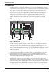
The MultiArrayIII™ user-configurable multiple-processor server farm (model MA3a) is designed
to consolidate up to nine network servers into a single system that can be mounted in a standard
19-inch rack enclosure. The MA3a contains a user-configurable 20-slot segmented backplane
that sits on the floor of the chassis. On the upper left front of the chassis sits an 8-bay, 3½"
vertical disk drive chassis. A combination 3½" floppy disk drive and 5¼" CD-ROM (both included
in the basic chassis) resides on the upper-right front. Dual redundant hot-swappable power
supplies make up the bottom of the front side. The configurable backplane allows you to
customize for unique applications and third-party components by combining segments. For
example, combining the first two segments into a 6-slot arrangement allows for a 32-port
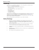
asynchronous data/fax communications server. The front of the MA3a is shown in Figure 1-1,
below.
115115
115115
E
G
H
I
C
B
A
D
F
F
J
J
Figure 1-1. MultiArrayIII
The vertical, 8-bay 3½" disk drive chassis (A) slides out for ease of installing and connecting
cables to the hard drives. Each subsegment has its own power switch (B) so that all the
components of a subsegment, including disk drives, can be independently powered on or off
(these features will be discussed in more detail later in this guide and in the MultiArray User
Guide). In addition, the muxing feature provides access to the CD-ROM and floppy drives via the
Binary Coded Decimal (BCD) display and muxing switch (C), allowing for smooth software
loading on all segments.
The horizontal drive chassis (D) contains a 3½" floppy disk drive and a 5¼" CD-ROM. In addition,
an open slot allows for the addition of an additional drive, i.e., a ninth hard drive or tape device.
The horizontal chassis also slides out for ease of drive installation and cable connections.
Individual segments access the CD-ROM and floppy drives via the muxing switch (C), which is
set to match the segment number for the appropriate SBC.
The power supply chassis located under the drive chassis contains two dual redundant hot-
swappable power supplies (E). The power supply area is located in the lower portion of the
chassis and is accessible from the front of the chassis. Power to the power supplies is controlled
by two master power switches (F) which light to indicate power, and each power supply module is
controlled by individual power switches (G). Power to each module is indicated by an LED (H)
and voltage switches on the individual modules (I) allow for selection of 115V or 230V operation.
The alarm reset switch (J) allows the alarm to be reset in the event of a power supply failure.