3000-Series Router/Multiport Data/Voice/Fax Frame Relay Access Device Models FR3060/3100 User Guide
User Guide 88302200 Revision A MultiFRAD 3000-Series (Model Numbers FR3060 and FR3100) This publication may not be reproduced, in whole or in part, without prior expressed written permission from Multi-Tech Systems, Inc. All rights reserved. Copyright © 1998, by Multi-Tech Systems, Inc. Multi-Tech Systems, Inc. makes no representations or warranties with respect to the contents hereof and specifically disclaims any implied warranties of merchantability or fitness for any particular purpose.
Contents Chapter 1 - Introduction and Description Introduction ................................................................................................................................................ 6 Preview of this Guide ................................................................................................................................. 6 Front Panel Description ............................................................................................................................
Data Port Statistics ................................................................................................................................... Frame Relay Statistics ....................................................................................................................... WAN Port Setup ....................................................................................................................................... Point to Point Setup ............................................
3000-Series Router/Multiport Data/Voice/Fax Frame Relay Access Device Chapter 1 - Introduction and Description
MultiFRAD 3000-Series User Guide Introduction Welcome to Multi-Tech's new MultiFRAD 3000 series, model numbers 3060 and 3100, a Frame Relay Access Device (FRAD) that encapsulates non-packetized data streams from serial and LAN devices into frame relay frames. The MultiFRAD 3000-Series features six or ten synchronous or asynchronous data channels, an IP/IPX router, and a composite link that connects to a common carrier frame relay network service or private frame relay network.
Chapter 1 - Introduction and Description Chapter 5 - Remote Configuration This chapter provides procedures for changing the configuration of a remote MultiFRAD. Remote configuration allows you to change the configuration of a unit by simply connecting a PC with communications software to a remote MultiFRAD that has communications software and a modem connected to the command port. You can then configure the unit. Chapter 6 - Router Management Chapter 6 describes a typical Telnet Client application.
MultiFRAD 3000-Series User Guide Front Panel Description The front panel of the MultiFRAD contains three main groups of LEDs that provide the information on the LAN connections, Voice/Fax channel activity (not currently available), and the general status of the MultiFRAD.
Chapter 1 - Introduction and Description Voice/Fax Channels 1 - 8 Note: the Voice/Fax Channels are not currently supported. FXS Foreign Exchange Station. This indicator lights when the voice/fax channel is configured for FXS operation. FXO Foreign Exchange Office. This indicator lights when the voice/fax channel is configured for FXO operation. E&M Ear & Mouth Operation. This indicator lights when the voice/fax channel is configured for E&M operation. FAX Fax.
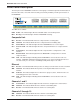
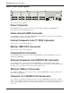
MultiFRAD 3000-Series User Guide Back Panel Description VOICE/ FAX CHANNEL 8 VOICE/ FAX CHANNEL 7 E&M VOICE/ FAX CHANNEL 4 FXO FXS VOICE/ FAX CHANNEL 6 E&M FXO FXS VOICE/ FAX CHANNEL 3 VOICE/ FAX CHANNEL 5 E&M FXO FXS VOICE/ FAX CHANNEL 2 E&M FXO INTERNAL COMPOSITE LINK FXS VOICE/ FAX CHANNEL 1 MONITOR XMT RCV T1 DSU GND CHANNEL 10 CHANNEL 8 CHANNEL 6 CHANNEL 4 CHANNEL 2 (RS232/V.35) CHANNEL 9 CHANNEL 7 CHANNEL 5 CHANNEL 3 CHANNEL 1 (RS232/V.
Chapter 1 - Introduction and Description Channels 3 - 10 Connectors These DB-25 female connectors are used to connect the MultiFRAD to channel devices. These connections can be to either asynchronous or HDLC synchronous RS232 data equipment such as multiplexers. Voice/Fax Channels 1 - 8 Connectors Note: the Voice/Fax connectors are not currently supported.
MultiFRAD 3000-Series User Guide Technical Specifications • Provides access to frame relay networks for SLIP, PPP, async and HDLC sync devices. • Trunk and Data ports may be configured as EIA-232 or V.35 • Trunk Speeds up to T1/E1 synchronous • 4MB DRAM • 1MB of flash memory Ethernet Port • One Ethernet Interface - 10Base-T (twisted Pair) RJ-45 connector Command Port • Single 19.2Kbps asynchronous Command Port with a DB-25 female connector Composite Link (external) • Access Rate: 1.
3000-Series Router/Multiport Data/Voice/Fax Frame Relay Access Device Chapter 2 - Installation
MultiFRAD 3000-Series User Guide Introduction This chapter will guide you through the unpacking and installation of your MultiFRAD. The installation procedure, which is preceded by important safety instructions, will provide step by step instruction on cabling and powering-on the MultiFRAD. Chapter 3 will provide instruction on loading and configuring the MultiFRAD software. Unpacking your MultiFRAD 3000 Remove all items from the box.
Chapter 2 - Installation Cabling your MultiFRAD 3000 Cabling your MultiFRAD involves making the proper Power, Command Port, Ethernet, and Channel connections. Figure 3 shows the back panel connectors and the associated cable connections. The MF3060 supports up to 6 data channels and the MF3100 supports up to 10 data channels. The MF 3060 cannot be upgraded to support 10 channels. Table 1 details the procedures for connecting the cables to your MultiFRAD.
MultiFRAD 3000-Series User Guide 4 Connect the MultiFRAD to a PC using an appropriate RS232 cable. Plug the male end of the cable into the Command Port on the back of the MultiFRAD and the other end into the pc’s serial port. See Figure 3. 5 Connect one end of the power supply to a live AC outlet and connect the other end to the MultiFRAD as shown in Figure 3. The power connector is a 7-pin circular DIN connector.
3000-Series Router/Multiport Data/Voice/Fax Frame Relay Access Device Chapter 3 - Software Loading and Configuration
MultiFRAD 3000-Series User Guide Introduction This chapter will guide you through the installation and initial configuration of the MultiFRAD software included in your shipping box. Chapter 4 will provide a more detailed description of the software and it’s features. Loading your Software The following loading procedure does not provide every screen or option in the process of installing the MultiFRAD software.
Chapter 3 - Software Loading and Configuration 5. You may choose the Destination Location of your MF3000 software or you can choose the default destination by clicking on the Next button. If you click on the Browse button you can choose from several. It is recommended to choose the default destination. 6. Do you want to download default setup? dialog box is displayed. Click on the Yes button to continue. 7.
MultiFRAD 3000-Series User Guide If your network protocol is IPX, continue with the following steps. If you are not using IPX routing, click on IPX Routing Enable check box to disable IPX, then click on the OK button, and proceed to step 13. 9. Router Name: You can use the default Router Name or you can assign a new Router Name in this field. If you assign a new Router Name, it must be a printable ASCII string of a maximum of 47 characters.
Chapter 3 - Software Loading and Configuration 14. To change the IP parameters, proceed to the next step. If you are not using IP routing, click on the IP Routing Enable check box to disable IP routing and proceed to step 20 (the WAN Ports Default Setup). 15. The default Ethernet IP Address has to be changed to your unique LAN address. Assign an acceptable unique IP address to the Ethernet port. 16. Change the default Subnet Mask and Frame Type to the values you have assigned to your LAN port. 17.
MultiFRAD 3000-Series User Guide If your data device is an Asynchronous device, then click on Asynchronous check box, and set the Baud Rate by clicking on the Baud Rate down arrow and the drop down list box displays the baud rate. Also, select the Word Length, Parity, Stop Bits, etc. for your device. Refer to the user documentation for the parameters of the data device. 23. Click on OK when you are satisfied with your data port configurations. 24.
Chapter 3 - Software Loading and Configuration 26. Click on the OK button, the Frame Relay DLCI Default Setup dialog box is displayed with the all the groups active and your DLCI displayed in the DLCIs field. You can map a protocol stack and/or data port to a DLCI. 27. To map this DLCI to a protocol stack, click on a protocol stack’s down arrow for each protocol that your LAN is using.
MultiFRAD 3000-Series User Guide The Setup utility is "Ready to Download default setup Choose OK to proceed." Click on OK to proceed. 37. Writing Setup dialog box is displayed as the setup configuration is written to the MultiFRAD. 38. After the setup is written to the MultiFRAD, the unit is rebooted. 39. Check to ensure that the BTG LED on the MultiFRAD is Off after the download is complete and the MultiFRAD is rebooted. 40. Win3.
Chapter 3 - Software Loading and Configuration 42. From the main Setup dialog box, click on the Frame Relay button. 43. A Frame Relay dialog box stating “MultiFRAD has detected and added following DLCIs” is displayed. Click on the OK button. 44. A second Frame Relay dialog box is displayed, stating “MultiFRAD has detected Management Type to be Annex A. Hence it has set Management type to Annex A from Annex D”. The Management Types are Annex A, Annex D, or LMI. Any one could appear in this dialog box.
MultiFRAD 3000-Series User Guide 45. Click on a DLCI that you want to map. The Mappings, Map Data Ports, and all the other groups become active. 46. To map this DLCI to a protocol stack, click on a protocol stack’s down arrow for each protocol that your LAN is using. When you click on the down arrow for a protocol, the listing displays None and your logical IP WAN addresses and/or logical IPX network numbers. 47.
3000-Series Router/Multiport Data/Voice/Fax Frame Relay Access Device Chapter 4 - MultiFRAD Software
MultiFRAD 3000-Series User Guide Introduction This chapter describes the MultiFRAD 3000 software from an applications approach in how the configuration can be changed with recommendations on the impact of that change. The major configuration parameters were set during your loading of the software and downloading of your configuration at the end of the software installation. The MultiFRAD 3000 software is designed for the Microsoft ® Windows ® environment.
Chapter 4 - MultiFRAD Software Setup Menu The MultiFRAD 3000-Series Setup menu consists of 12 buttons in which you can point and click, an Events window in the middle of the menu, and a status bar at the bottom of the menu. The 12 buttons allow you to display and change the protocol stacks, statistics, WAN port setup, Frame Relay parameters, data port configuration, enable applications such as SNMP Agent, Telnet Server, WEB Server, and assign a MultiFRAD password.
MultiFRAD 3000-Series User Guide IP Setup The IP Setup dialog box allows you change the IP routing capabilities, add or delete logical WANs, enable the DHCP relay agent, assign DNS address, and define default and static routes. The initial routing capabilities were established during the software installation. You can change IP routing parameters by clicking on the Advanced tab and changing, for example, the RIP Response Time or RIP Route Aging Time.
Chapter 4 - MultiFRAD Software To add logical WAN in a frame relay configuration, click on the Add(+) button and the next WAN number is displayed in the List of Logical WANs window on the left side of the WAN dialog box. To delete the last logical WAN assigned, click on the Delete (-) button. The Advanced IP Setup dialog box controls the timers, Dynamic Host Configuration Protocol (DHCP) and Domain Name System (DNS) options, the default route, filters, and Static Routes.
MultiFRAD 3000-Series User Guide IPX Setup The IPX Setup dialog box controls the four frame types, the WAN ports setup, and the advanced tab enables IPX routing, auto learn of Ethernet network numbers, and the distributed name of the MultiFRAD. The RIP and SAP default timers should not have to be changed for most applications. Disabling IPX and SPX Watchdog Spoofing in the Bandwidth Optimization group has proven effective under certain circumstances with Citrix clients.
Chapter 4 - MultiFRAD Software The IPX WAN network number has to be the same on both ends of the link and must be unique throughout the internetwork. If the WAN port is configured in a point to point configuration, both WAN network numbers have to be the same and unique. If the WAN port is configured in a frame relay configuration, both virtual WAN numbers have to be the same and unique.
MultiFRAD 3000-Series User Guide Spanning Tree Setup The Spanning Tree Setup dialog box controls transparent bridging when the Bridging option is enabled or if there are any loops or redundant links in the internetwork, then Spanning Tree Algorithm option must be used. Spanning Tree is a method of transparent bridging, as opposed to source route bridging which the MultiFRAD does not support. The MultiFRAD defaults with one logical WAN port mapped to a DLCI.
Chapter 4 - MultiFRAD Software Statistics The Statistics dialog box allows you to view statistics on the major events of the MultiFRAD. The Statistic dialog box changes depending on the way the WAN port is configured. If the MultiFRAD is configured in a point-to-point configuration, the button to the right of the WAN changes to PPP and the DLCI button will be grayed out.
MultiFRAD 3000-Series User Guide IP Statistics IP is a connection-less network protocol that resides in the network layer of a conventional OSI layered model (for more information on this model, refer to Appendix C). Depending on what is going on at the application layer, IP will typically use one of two transport layer protocols.
Chapter 4 - MultiFRAD Software IPX Port Statistics The IPX Port Statistics dialog box displays information pertaining to the IPX Port, for example, the frame type used or the number of packets transmitted/received. IPX is a network layer protocol that is usually associated with Novell NetwareTM networks. It allows for encapsulation of four different frame types over a single physical LAN connection (provided each frame type has a unique network address): RAW (802.3), LLC (802.2), Ethernet II, and SNAP.
MultiFRAD 3000-Series User Guide STP (Spanning Tree) Port Statistics The STP (Spanning Tree) Port Statistics dialog box displays information regarding the selected STP port, for example, the number of frames discarded or forwarded. Spanning Tree transParent (STP) bridging is the method of bridging used by the MultiFRAD as specified in IEEE 802.1d standard.
Chapter 4 - MultiFRAD Software SNMP Statistics The SNMP Statistics dialog box provides statistical information on Simple Network Management Protocol (SNMP). SNMP is an application layer protocol that facilitates the exchange of management information between network devices. There are three key components in SNMP: the devices that are to be managed, agents, and the network management systems. The managed device is the network device, like a router.
MultiFRAD 3000-Series User Guide WAN Statistics The WAN Statistics dialog box provides statistical information regarding the MultiFRAD’s WAN port, including the number of packets transmitted/received, and total bytes transmitted/received. The WAN Port Statistics dialog box pertains to the traffic on the MultiFRAD’s composite link (WAN) port. The Statistics that fall into “Others” category relate to the physical layer between the MultiFRAD and the link device, i.e. the CSU/DSU.
Chapter 4 - MultiFRAD Software PPP Statistics The PPP Statistics dialog box provides statistical information related to Point-to-Pint Protocol (PPP). For example, this dialog box displays the current protocol and compression methods enabled. The statistics in this dialog box will only apply when you are accessing your network remotely with a PPP client. The Network Control Protocol (NCP) is the means by which PPP clients negotiate the network-layer protocols.
MultiFRAD 3000-Series User Guide Data Port Statistics The Data Port Statistics dialog box displays statistical information, such as bytes or blocks received/ transmitted, for the various data ports. This window shows the statistics for all data channels. By highlighting and double clicking on a particualr port, you can view the individual channel statistics, as well as various hardware signals (CTS, RTS, DSR, DCD, DTR) and XON/XOFF status.
Chapter 4 - MultiFRAD Software Frame Relay Statistics The Frame Relay Management Statistics dialog box can be a useful tool for troubleshooting MultiFRAD installations and monitoring the performance of active links, and determining if the MultiFRAD is talking to the provider’s switch. The Polling Details section lists the various management frames sent and received. For every Status Enquiry Sent, a Status Response should be received from the network.
MultiFRAD 3000-Series User Guide The DLCI Statistics dialog box shows the individual DLCI status and statistics. This information can be helpful in determining if the DLCI is active, if it is going up and down, and if the MultiFRAD is experiencing frame relay network congestion (FECN/BECN). It also gives an indication of the momentary throughput on individual DLCIs.
Chapter 4 - MultiFRAD Software WAN Port Setup The WAN Port Setup dialog box controls how the port is configured (i.e., frame relay or point-topoint). If the WAN port is configured for frame relay, then the mode of the port is synchronous. If the port is configured for point-to-point, then the mode can be either synchronous or asynchronous. If the mode is asynchronous, then the connection method can be either answering or dialing.
MultiFRAD 3000-Series User Guide Point to Point Setup The Point to Point Setup dialog box controls the WAN port protocol, dial on demand, and remote port setup. The WAN port protocol can be either Point to Point Protocol (PPP) or Serial Line Internet Protocol (SLIP). PPP is the more robust of the two protocols in that it allows the end-points to negotiate use of the link and protocol parameters in a standardized way and also allows for standardized encapsulation of the packets.
Chapter 4 - MultiFRAD Software Frame Relay Setup The Frame Relay dialog box displays the CIR Measurement Interval in milliseconds, the Management Type and details of that management type, and the number of DLCI’s that are active. The MultiFRAD can detect DLCIs and the Management Type when you are connected to an active frame relay service. So it is important that if you change any frame relay parameters, that the new parameters agree with the way your frame relay service is provisioned.
MultiFRAD 3000-Series User Guide If you click on the DLCI button on the right side of the dialog box, the Frame Relay DLCI dialog box is displayed. If you have connected to a frame relay service, this dialog box should display your current DLCI numbers automatically. It also shows the protocol mapping of the high lighted DLCI, which data port it is mapped to, and how you set up your Congestion Management, Mode, CIR, and Be values.
Chapter 4 - MultiFRAD Software When a DLCI has just been detected, or if you have just made a new DLCI, it has not yet been mapped to a protocol address or a data port. The default Congestion Management, mode, CIR, and Be are displayed. You should verify these default setting with how your new DLCI is provisioned by you service provider. Congestion Management, Mode, and CIR/Be settings are used to avoid congestion and possible loss of data.
MultiFRAD 3000-Series User Guide To map a new DLCI (e.g., 17) to a protocol, return to the Main Menu and then click on the protocol stack that you are using. In the lower left part of the protocol stack dialog box a list of Logical WANs is displayed. To add a new logical WAN, click on the Add (+) button and the next logical WAN number will appear in the list on the left hand side of the dialog box. For example lets map our new DLCI 17 to the IP protocol as a WAN 2 with an IP Port Address of 200.2.11.
Chapter 4 - MultiFRAD Software We now have WAN IP address 200.2.11.1 from the IP protocol stack mapped to DLCI 17. Let’s say we also want to map a data channel to DLCI 17. The data ports that are already mapped to other DLCIs are grayed out. In our example, lets map data port 3to DLCI 17. Simply click on Port 3 in the Data Port Mappings group and an X appears in the box at the left of Port 3. Now we have both data port 3 and IP WAN address 200.2.11.1 mapped to DLCI 17.
MultiFRAD 3000-Series User Guide Data Port Configuration The Data Port Configuration dialog box allows you to change the parameters of the data transferred between the data device and the MultiFRAD. The MultiFRAD can transfer data between the data device and MultiFRAD in either a synchronous or asynchronous mode. If your data device is an asynchronous device, choose the Configure Asynchronous option and configure the MultiFRAD to match your device.
3000-Series Router/Multiport Data/Voice/Fax Frame Relay Access Device Chapter 5 - Remote Configuration
MultiFRAD 3000-Series User Guide Introduction This chapter provides procedures for changing the configuration of a remote unit. Remote configuration allows a PC at one site (local site) to dial a remote MultiFRAD and change the configuration of that remote unit. Remote configuration can be accomplished either directly through the LAN or remotely using modems.
Chapter 5 - Remote Configuration In the Dial String field, enter the AT command for dialing (ATDT) plus the phone number of the remote MultiFRAD. If your Modem Initialization String, Initialization Response, or Connect Response values are different than the defaults in the dialog box, refer to your modem user documentation and change the default values to match your modem. Click on OK when you are satisfied with your selections. 6 You are returned to the Windows program.
MultiFRAD 3000-Series User Guide LAN-Based Remote Configuration Windows Sockets Compliant TCP/IP Stack The configuration program requires a Windows Sockets compliant TCP/IP stack. Microsoft provides a TCP/IP stack free for Windows for Workgroups 3.11. TCP/IP protocol software must be installed and functional before the configuration program can be used. 1 You must assign an internet (IP) address for the PC and for each node that will be managed by the configuration program.
Chapter 5 - Remote Configuration 6 The MultiFRAD Setup dialog box is then displayed. This is the dialog box of the remote MultiFRAD. You can select any of the Protocol Stacks, Device drivers, or other buttons and change the configuration of the remote MultiFRAD. Refer Chapter 4 for a description of the MultiFRAD software. For definitions of each dialog box or fields within a dialog box, refer to the on-line helps provided in the MultiFRAD software.
MultiFRAD 3000-Series User Guide 58
3000-Series Router/Multiport Data/Voice/Fax Frame Relay Access Device Chapter 6 - Router Management
MultiFRAD 3000-Series User Guide Introduction A typical Telnet client application, and typical WEB-browser management of the MultiFRAD are described in this chapter. The MultiFRAD has a built-in Telnet Server for access through Telnet clients. A typical Telnet client is allowed to configure the MultiFRAD and its data ports. In addition, the MultiFRAD can be remotely accessed and configured from anywhere on the internet through its WEB interface.
Chapter 6 - Router Management MultiFRAD Configuration The MultiFRAD Configuration option allows you to view and change parameters on the protocol stacks, high and low level device drivers, enable or disable the supported servers, configure MUX data ports, set up filtering and priority, or view system information. To select an option, enter the number of the option and hit the Enter key. For example, to select the Protocol Stacks option, type 1 .
MultiFRAD 3000-Series User Guide WEB Browser Management The MultiFRAD can be accessed from anywhere on the connected internet via the built-in WEB Browser interface. You must check this option in Other setup to enable the function. Depending on the rights of the user (read/write, or read only), it is possible to view the current parameters and statistics of the MultiFRAD as well as configure and download setup changes to the MultiFRAD.
Chapter 6 - Router Management Note: the first user to access the MultiFRAD will have read/write rights over the unit. All subsequent users will have read only rights, and therefore, some of the options within the WEB interface will be inactive (i.e., will not be linked). From the MultiFRAD 3000 Configuration menu, you can access current settings and view statistics, as well as configure and download a new setup to the MultiFRAD.
MultiFRAD 3000-Series User Guide 64
3000-Series Router/Multiport Data/Voice/Fax Frame Relay Access Device Chapter 7 - Warranty, Service and Tech Support
MultiFRAD 3000-Series User Guide Introduction This chapter will provide you the resources for receiving service or support for your MultiFRAD. The chapter starts with a description of the warranty, and continues with instructions for contacting the Service department, Technical Support group, and various Multi-Tech internet resources. Limited Warranty Multi-Tech Systems, Inc.
Chapter 7 - Warranty, Service and Tech Support Tech Support Multi-Tech has an excellent staff of technical support personnel available to help you get the most out of your Multi-Tech product. If you have any questions about the operation of this unit, call 1-800-9722439. Please fill out the MultiFRAD information (below), and have it available when you call. If your MultiFRAD requires service, the tech support specialist will guide you on how to send in your equipment (refer to the next section).
MultiFRAD 3000-Series User Guide Service If your tech support specialist decides that service is required, your MultiFRAD may be sent (freight prepaid) to our factory. Return shipping charges will be paid by Multi-Tech Systems. Include the following with your MultiFRAD: • a description of the problem. • return billing and return shipping addresses. • contact name and phone number. • check or purchase order number for payment if the MultiFRAD is out of warranty.
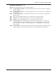
Chapter 7 - Warranty, Service and Tech Support To Download a file If you know the file name 1. 2. 3. 4. 5. 6. 7. 8. From the Main Menu, type F to access the Files Menu, then type D. Enter the name of the file you wish to download from the BBS. If a password is required, enter the password. Answer Y or N to the automatic logoff question. Select a file transfer protocol by typing the indicated letter, such as Z for Zmodem (the recommended protocol).
MultiFRAD 3000-Series User Guide About CompuServe In addition to the BBS, Multi-Tech provides support through CompuServe’s Modem Vendor Forum (GO MODEMVEN). Refer to your CompuServe documentation for special operating procedures. About the Internet Multi-Tech is a commercial user on the Internet, and we retrieve messages from our customers on a periodic basis. Multi-Tech’s presence includes a Web site at: http://www.multitech.com and an ftp site at: ftp://ftp.multitech.
3000-Series Router/Multiport Data/Voice/Fax Frame Relay Access Device Appendices
MultiFRAD 3000-Series User Guide Appendix A - Cabling Diagrams Command Port Cable 13 25 12 11 24 10 23 PIN NO. To COMMAND PORT Connector 9 22 8 21 20 7 6 19 5 18 4 17 3 16 15 14 PIN NO.
Appendix A - Cabling Diagrams Trunk Cable 13 12 25 11 24 10 23 9 22 8 7 21 20 6 19 5 18 4 17 3 16 2 15 1 14 RS232C/V.24 * Link Cable PIN NO. To External Synchronous Modem/DSU Connector PIN NO. 1 1 2 2 3 3 4 4 5 5 7 7 8 8 15 15 17 17 20 20 25 25 CHASSIS GROUND (AA) TRANSMIT DATA (BA) RECEIVE DATA (BB) REQUEST TO SEND (CA) CLEAR TO SEND (CB) To MultiRouter Link 1,2 or 3 RS232C/V.
MultiFRAD 3000-Series User Guide Remote Configuration Cable PIN NO. To COMMAND PORT Connector 1 1 FRAME GROUND 2 2 TRANSMIT DATA (TX) 3 3 RECEIVE DATA (RX) 4 4 REQUEST TO SEND (RTS) 5 5 CLEAR TO SEND (CTS) 6 6 7 7 8 8 20 20 22 22 25 Male 74 PIN NO. 25 Male SIGNAL GROUND To DCE Device (Communication Device i.e.
Appendix B - Regulatory Information Appendix B - Regulatory Information Note: This equipment has been tested and found to comply with the limits for a Class A digital device, pursuant to Part 15 of the FCC Rules. These limits are designed to provide reasonable protection against harmful interference when the equipment is operated in a commercial installation.
MultiFRAD 3000-Series User Guide Appendix C - Network Overview Network architecture defines how computer equipment and other devices are linked together to form a communications system that allows users to share information and resources. There are proprietary network architectures and open architectures like the Open Systems Interconnection (OSI) model defined by the International Organization for Standardization (ISO).
Appendix C - Network Overview The transport layer provides a high level of control for moving information between systems, including more sophisticated error handling, prioritization, and security features. It provides quality service and accurate delivery by providing connection-oriented services between two end systems. The transport layer controls the sequence of packets, regulates traffic flow, and recognizes duplicate packets.
MultiFRAD 3000-Series User Guide In general, a packet is a collection of information that contains data (payload) and headers (pilot). Headers include the source and destination address as well as control information to handle errors and keep packets flowing properly. Each packet is a separate block of information that can have a different destination address, and in some cases, different sizes.
Appendix C - Network Overview IP Addressing Every node on an IP network requires a 4-byte numeric address that identifies both a network and a local host or node on the network. This address is written as four numbers separated by dots, for example, 148.1.9.1. In most cases, the network administrator sets up these addresses when installing a device.
MultiFRAD 3000-Series User Guide 80
3000-Series Router/Multiport Data/Voice/Fax Frame Relay Access Device Glossary
MultiFRAD 3000-Series User Guide A Access: The T1 line element made up of two pairs of wire that the telephone company brings to the customer premises. The Access portion ends with a connection at the local telco (LEC or RBOC). Accunet Spectrum of Digital Services (ASDS): The AT&T 56K bps leased (private) line service. Similar to services of MCI and Sprint. ASDS is available in nx56/64K bps, where n=1, 2, 4, 6, 8, 12.
Glossary Backward Explicit Congestion Notification (BECN): A bit that tells you that a certain frame on a particular logical connection has encountered heavy traffic. The bit provides notification that congestion-avoidance procedures should be initiated in the opposite direction of the received frame. See also FECN (Forward Explicit Congestion Notification). Basic Rate Interface (BRI): An ISDN access interface type comprised of two B-channels each at 64K bps and one D-channel at 64K bps (2B+D).
MultiFRAD 3000-Series User Guide Centrex: A multi-line service offered by operating telcos which provides, from the telco CO, functions and features comparable to those of a PBX for large business users. See also "Private Branch Exchange", "Exchange". Channel: A data communications path between two computer devices. Can refer to a physical medium (e.g., UTP or coax), or to a specific carrier frequency.
Glossary Data Service Unit (DSU): A device that provides a digital data service interface directly to the data terminal equipment. The DSU provides loop equalization, remote and local testing capabilities, and a standard EIA/CCITT interface. Dedicated Line: A communication line that is not switched. The term leased line is more common. Default: This is a preset value or option in software packages, or in hardware configuration, that is used unless you specify otherwise.
MultiFRAD 3000-Series User Guide Excess Zeros: A T1 error condition that is logged when more than 15 consecutive 0s or less than one 1 bit in 16 bits occurs. Exchange: A unit (public or private) that can consist of one or more central offices established to serve a specified area. An exchange typically has a single rate of charges (tariffs) that has previously been approved by a regulatory group.
Glossary Frame Relay Forum: A non-profit organization of 300+ vendors and service providers, based in Foster City, CA, that are developing and deploying frame relay equipment. Frame Relay Implementors Forum: A group of companies supporting a common specification for frame relay connection to link customer premises equipment to telco network equipment. Their specification supports ANSI frame relay specs and defines extensions such as local management.
MultiFRAD 3000-Series User Guide ISA (Industry Standards Architecture) (pronounced "ice a"): The classic 8 or 16-bit architecture introduced with IBM's PC-AT computer. ISDN (Integrated Services Digital Network): An International telecommunications standard for transmitting voice, video and data over a digital communications line. ISDN is a world-wide telecommunications service that uses digital transmission and switching technology to support voice and digital data communications.
Glossary Long Haul: The T1 element that connects to the Access portion of the long distance company's (LDC's) central office. The LDC is commonly called the point of presence (POP). Each LDC has a number of POPs, located throughout the country. The LDC is also called an IEC (Inter Exchange Carrier). Long Haul Communications: The type of phone call reaching outside of a local exchange (LE).
MultiFRAD 3000-Series User Guide Outage: The measure of the time during which a circuit is not available for use due to service interrupt. Outage is the complement of circuit "availability" (100% minus % available = % outage). Out-of-band: Signaling that is separated from the channel carrying the information (i.e., the voice/data/video signal is separate from the carrier signal). Dialing and various other "supervisory" signals are included in the signaling element. Contrast "In-band" signaling.
Glossary Pulse dialing: One of two methods of dialing a telephone, usually associated with rotary-dial phones. Compare with "tone dialing". Q Quantizing: The process of analog-to- digital conversion by assigning a range, from the contiguous analog values, to a discrete number. R Random Access Memory (RAM): A computer's primary workspace. All data must be stored in RAM (even for a short while), before software can use the processor to manipulate the data.
MultiFRAD 3000-Series User Guide Signaling: The process of establishing, maintaining, accounting for, and terminating a connection between two endpoints (e.g., the user premises and the telco CO). Central office signals to the user premises can include ringing, dial tone, speech signals, etc. Signals from the user's telephone can include off-hook, dialing, speech to far-end party, and on-hook signals. In-band signaling techniques include pulse and tone dialing.
Glossary T1 Mux: A device used to carry many sources of data on a T1 line. The T1 mux assigns each data source to distinct DS0 time slots within the T1 signal. Wide bandwidth signals take more than one time slot. Normal voice traffic or 56/64K bps data channels take one time slot. The T1 mux may use an internal or external T1 DSU; a "channel bank" device typically uses an external T1 CSU.
MultiFRAD 3000-Series User Guide 94
Index Index A About CompuServe ...................................................................................................................................... 70 About the Internet ......................................................................................................................................... 70 About the Multi-Tech Fax-Back Service ........................................................................................................ 70 B Back Panel Description ..........
MultiFRAD 3000-Series User Guide IP Addressing ............................................................................................................................................... 79 IP Setup ........................................................................................................................................................ 30 IP Statistics ..........................................................................................................................................
Index P Packet .......................................................................................................................................................... 77 Point to Point Setup ...................................................................................................................................... 46 PPP Statistics ...............................................................................................................................................
MultiFRAD 3000-Series User Guide Electrical/Physical ..................................................................................................................................... 12 EtherNet Port ............................................................................................................................................ 12 Requirement .............................................................................................................................................