® MultiModem ZBA MT9234ZBA‐USB‐CDC User Guide
MultiModem ZBA User Guide MT9234ZBA‐USB‐CDC S000473B Revision B Copyright All rights reserved. This publication may not be reproduced, in whole or in part, without prior expressed written permission from Multi‐Tech Systems, Inc. Copyright © 2012 by Multi‐Tech Systems, Inc. Multi‐Tech Systems, Inc. makes no representations or warranties with respect to the contents hereof and specifically disclaims any implied warranties of merchantability or fitness for any particular purpose.
Contents Chapter 1 – Product Overview ..................................................................................................................... 5 Feature Overview .................................................................................................................................................... 5 Package Contents ...................................................................................................................................................
Contents Appendix A – Regulatory Compliance .......................................................................................................24 FCC Part 68 Telecom .............................................................................................................................................24 FCC Part 15 Regulation .........................................................................................................................................25 Canadian Limitations Notice ......
Chapter 1 – Product Overview Thank you for using the MultiModem ZBA‐USB modem. Your MultiModem product data/fax modem supports remote configuration and dial‐up connections. It offers V.34/33.6K fax and Error Correction Mode that reduces fax transmission time by more than half when compared to traditional fax modems. In addition, these modems are globally approved for use in many countries around the world. Feature Overview ● V.92/56K download speeds and 48K upload speeds when connecting with V.
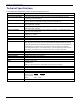
Chapter 1 – Product Overview Technical Specifications Your MultiModem ZBA‐USB‐CDC modem has the following specifications.
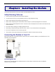
Chapter 2 – Installing the Modem This chapter describes how to set up your Multi‐Tech MultiModem product. Safety Warning Telecom ● Use this product only with UL and cUL listed computers. ● To reduce the risk of fire, use only 26 AWG (.41 mm) or larger telephone wiring. ● Never install telephone wiring during a lightning storm. ● Never install a telephone jack in wet locations unless the jack is specifically designed for wet locations.
Chapter 2 – Installing the Modem Connecting the Line Plug one end of the phone cable into the modem’s LINE jack and the other end into a phone line wall jack. Note: The LINE jack is not interchangeable with the PHONE jack. Do not plug the phone into the LINE jack or the line cable into the PHONE jack. Note: The Federal Communications Commission (FCC), and Industry Canada impose certain restrictions on equipment connected to public telephone systems. See Appendix A for more information. .
Chapter 2 – Installing the Modem Installing the Modem Driver After the installation has been completed, you should test the operation of your new MT9234ZBA‐USB by registering it. Key in the URL given below and follow the on‐line instructions: http://www.multitech.com/en_US/TOOLS/Forms/register/warranty.asp Manually Installing the MT9234ZBAUSBCDC in Windows 7 After connecting your MT9234ZBA‐USB‐CDC to an available USB port, Windows 7 reports that the driver software was not successfully installed.
Chapter 2 – Installing the Modem 4. In the list of devices, find an item called MT9234ZBA‐USB‐CDC. Right‐click on this item and select Update Driver Software. 5. Left‐click the option Browse my computer for driver software.
Chapter 2 – Installing the Modem 6. Click Browse and navigate to the folder containing the appropriate drivers for your install (either 34‐bit or 64‐bit). Click OK. 7. Click Next to continue the installation.
Chapter 2 – Installing the Modem 8. A Windows Security window stating that the publisher cannot be verified might appear. If so, click Install this driver software anyway. 9. A transitory window opens as the installation completes. 10. To finish installing, click Close. 11. After installing, ensure the MT9234ZBA‐USB is working by registering it. To do so, go to the following website and follow the instructions there: http://www.multitech.com/en_US/TOOLS/Forms/register/warranty.
Chapter 2 – Installing the Modem Installing the Modem Driver for use with Windows Vista 1. Power up your computer. 2. If you have not already done so, connect the modem’s USB cable to a USB port on the computer and connect the phone line between the modem and a telephone wall jack. 3. Windows detects that the new modem is present and start the New Hardware wizard. Select the ‘Locate and install driver software (recommended)’ option.
Chapter 2 – Installing the Modem Installing the Modem in Windows Server 2008, 2003 and XP This installation assumes a Windows Server 2008, XP, or 2003 operating system. The steps that follow use the Windows XP operating system. The other operating systems use sequences and windows similar to Windows XP. 1. Connect the USB cable between the MultiModem and the PC. 2.
Chapter 2 – Installing the Modem 4. The Please choose your search and installation options wizard pane opens. Select Include this location in the search. 5. Click Browse. Then navigate to the location where you stored the driver you downloaded. 6. Click Next. The Please wait while the wizard searches for the MT9234ZBA‐CDC wizard pane appears.
Chapter 2 – Installing the Modem 7. You may be prompted by the Windows Logo check. It is safe to continue (select to Continue Anyway) as the installation file has passed certification testing for Windows Vista (all other operating systems may display a certification warning). 8. The Please wait while the wizard installs the software wizard pane appears.
Chapter 2 – Installing the Modem 9. At the ‘Completing the Found New Hardware Wizard’ screen for the MultiMobile MT9234ZBA‐CDC click Finish. Installation is complete. After installing the modem and setting up Internet access, ensure the modem works by registering it. To do so, go to the following website and follow the instructions there: http://www.multitech.com/en_US/TOOLS/Forms/register/warranty.
Chapter 2 – Installing the Modem Configuring the Country Where Modem is Used Different countries have different requirements for how modems must function. Therefore, before you use your modem, you must configure it to match the defaults of the country in which you are using it.
Chapter 3 – Operating the Modem Front Panel Overview The MultiModem product has 6 LED indicators on the front panel that indicate status, configuration, and activity. Transmit Data. The TD LED flashes when the modem is transmitting data to another modem. Receive Data. The RD LED flashes when the modem is receiving data from another modem. Carrier Detect. The CD LED lights when the modem detects a valid carrier signal from another modem.
Chapter 4 – Remotely Configuring the Modem This chapter describes how to use a network management tool to configure modems anywhere in your network from one location. With password protected remote configuration, you can issue AT commands to a remote MultiModem product for maintenance or troubleshooting as if you were on site. This chapter also describes how to change default passwords and characters to enhance the security of the product.
Chapter 5 – Troubleshooting Your modem was tested before it was shipped to you. If you can’t make a successful connection, or if you experience data loss or garbled characters during your connection, it is possible that the modem is defective. However, it is more likely that the source of your problem lies elsewhere. The following symptoms are typical of problems you might encounter: ● None of the LEDs light when the modem is on. ● The modem does not respond to commands.
Chapter 5 – Troubleshooting The Modem Doesn’t Work with Caller ID ● Caller ID information is transmitted between the first and second rings, so if autoanswer is turned off (S0=0) or if the modem is set to answer after only one ring (S0=1), the modem does not receive Caller ID information. Check your initialization string, and if necessary change it to set the modem to answer after the second ring (S0=2). ● Make sure that you have Caller ID service from your telephone company.
Chapter 5 – Troubleshooting ● If the modem reports NO CARRIER, the phone was answered at the other end, but no connection was made. You might have dialed a wrong number, and a person answered instead of a computer, or you might have dialed the correct number, but the other computer or software was turned off or faulty. Check the number and try again, or try calling another system to make sure your modem is working. Also, try calling the number on your telephone.
Appendix A – Regulatory Compliance FCC Part 68 Telecom 1. This equipment complies with part 68 of the Federal Communications Commission Rules. On the outside surface of this equipment is a label that contains, among other information, the FCC registration number. This information must be provided to the telephone company. 2. The suitable USOC jack (Universal Service Order Code connecting arrangement) for this equipment is shown below.
Appendix A – Regulatory Compliance FCC Part 15 Regulation This equipment has been tested and found to comply with the limits for a Class B digital device, pursuant to 47 CFR – FCC Part 15 regulations. The stated limits in this regulation are designed to provide reasonable protection against harmful interference in a residential environment.
Appendix A – Regulatory Compliance This Class B digital apparatus meets all requirements of the Canadian Interference‐Causing Equipment Regulations. Cet appareil numérique de la classe B respecte toutes les exigences du ‐Reglement Canadien sur le ‐matériel brouilleur.
Appendix A – Regulatory Compliance International Modem Restrictions Some dialing and answering defaults and restrictions may vary for international modems. Changing settings may cause a modem to become non‐compliant with ‐national telecom requirements in specific countries. Also note that some software packages may have features or lack restrictions that may cause the modem to become non‐ compliant.
Appendix A – Regulatory Compliance Restriction of the Use of Hazardous Substances (RoHS) Multi‐Tech Systems, Inc. Certificate of Compliance 2002/95/EC Multi‐Tech Systems, Inc. confirms that this product now complies with the chemical concentration limitations set forth in the directive 2002/95/EC of the European Parliament (Restriction Of the use of certain Hazardous Substances in electrical and electronic equipment ‐ RoHS) These Multi‐Tech Systems, Inc.
Appendix B – Waste Electrical and Electronic Equipment July, 2005 The WEEE directive places an obligation on EU‐based manufacturers, distributors, retailers and importers to take‐ back electronics products at the end of their useful life. A sister Directive, ROHS (Restriction of Hazardous Substances) complements the WEEE Directive by banning the presence of specific hazardous substances in the products at the design phase.
Appendix C - C-ROHS HT/TS Substance Concentration 依照中国标准的有毒有害物质信息 根据中华人民共和国信息产业部 (MII) 制定的电子信息产品 (EIP) 标准-中华人民共和国《电子信息产品污染控制管理办法》(第 39 号),也称作中国 RoHS,下表列出了 Multi‐Tech Systems Inc.
Appendix D – ASCII Conversion ASCII Conversion Chart CTRL CODE HEX DEC @ NUL 00 0 A SOH 01 B STX C CODE HEX DEC CODE HEX DEC CODE HEX DEC SP 20 32 @ 40 64 ` 60 96 1 ! 21 33 A 41 65 a 61 97 02 2 " 22 34 B 42 66 b 62 98 ETX 03 3 # 23 35 C 43 67 c 63 99 D EOT 04 4 $ 24 36 D 44 68 d 64 100 E ENQ 05 5 % 25 37 E 45 69 e 65 101 F ACK 06 6 & 26 38 F 46 70 f 66 102 G BEL 07 7 ' 27 39 G 47 71 g 67 103
Appendix D – ASCII Conversion ETX End of Text SO Shift Out EM End of Medium EOT End of Transmission SI Shift In SUB Substitute ENQ Enquiry DLE Data Link Escape ESC Escape ACK Acknowledge DC1 Device Control 1 FS File Separator BEL Bell or Alarm DC2 Device Control 2 GS Group Separator BS Backspace DC3 Device Control 3 RS Record Separator HT Horizontal Tab DC4 Device Control 4 US Unit Separator LF Line Feed NAK Negative Acknowledge DEL Delete MT9234ZBA‐USB User G
Index A AT Commands ................................................................... 5 C Canadian regulations ........................................................ 25 Connecting the modem ...................................................... 7 D DOC regulations............................................................... 25 F FCC regulations ............................................................... 24 Front panel .......................................................................