® MultiModem ZBA MT9234ZBA‐USB User Guide
MultiModem ZBA User Guide MT934ZBA‐USB S000419E Revision E Copyright All rights reserved. This publication may not be reproduced, in whole or in part, without prior expressed written permission from Multi‐ Tech Systems, Inc. Copyright © 2011 by Multi‐Tech Systems, Inc. Multi‐Tech Systems, Inc. makes no representations or warranties with respect to the contents hereof and specifically disclaims any implied warranties of merchantability or fitness for any particular purpose.
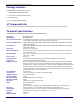
Contents Chapter 1 – Product Overview and Specifications ............................................................................................... 5 Features Overview ...................................................................................................................................................... 5 Universal Serial Bus (USB) ............................................................................................................................................
Contents South African Notice .................................................................................................................................................. 33 Appendix B – Waste Electrical and Electronic Equipment................................................................................... 34 Appendix C – C‐ROHS HT/TS Substance Concentration ...................................................................................... 35 Appendix D – Installing with Linux ...........
Chapter 1 – Product Overview and Specifications Congratulations on your purchase of the MultiModem ZBA‐USB modem. Your MultiModem product data/fax modem supports remote configuration and dial‐up connections. It offers V.34/33.6K fax and Error Correction Mode that reduces fax transmission time by more than half when compared to traditional fax modems. In addition, they are globally approved for use in many countries around the world. This means one model can ship virtually anywhere.
Chapter 1 –Product Overview and Specifications Package Contents The MultiModem USB package contains: ● A MultiModem data/fax modem ● A set of four self‐adhesive plastic feet ● One USB cable ● One modular telephone cable AT Commands Info The AT commands are published in a separate Reference Guide. Download this guide from the Multi‐Tech website.
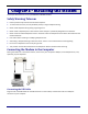
Chapter 2 – Installing the Modem This chapter describes how to set up MultiModem ZBA‐USB modems. Safety Warning Telecom ● Use this product only with UL and cUL listed computers. ● To reduce the risk of fire, use only 26 AWG (.41mm) or larger telephone wiring. ● Never install telephone wiring during a lightning storm. ● Never install a telephone jack in wet locations unless the jack is specifically designed for wet locations.
Chapter 2 – Installing the Modem Connecting the Phone Line Plug one end of the phone cable into the modem’s LINE jack and the other end into a phone line wall jack. Note: The LINE jack is not interchangeable with the PHONE jack. Do not plug the phone into the LINE jack or the line cable into the PHONE jack. Note: The Federal Communications Commission (FCC), and Industry Canada impose certain restrictions on equipment connected to public telephone systems. See Appendix A for more information.
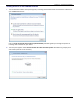
Chapter 2 – Installing the Modem Installing the Driver for the TUSB3410 Serial Port 1. The Found New Hardware wizard panel appears, indicating that Windows needs to install driver software for your TUSB3410 Serial Port. Click on Locate and install driver software (recommended). Windows guides you through the process of installing driver software for your device. 2. The next pane appears. Select I don’t have the disc. Show me other options.
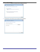
Chapter 2 – Installing the Modem 3. In the next pane, click Browse my computer for driver software (advanced). 4. At the Browse for driver software on your computer wizard, click Browse. 10 Multi‐Tech Systems, Inc.
5. Chapter 2 – Installing the Modem In the dialog box that appears, navigate to the area where you stored the drivers you downloaded from the Multi‐Tech website. Click OK. Then click Next. 6. The Would you like to install this device software? pane appears. Click Install. 7. The Installing driver software… pane appears, showing the installation’s progress. Multi‐Tech Systems, Inc.
Chapter 2 – Installing the Modem 8. A wizard pane appears to tell you that the software is now successfully installed. Click Close. Installing the Modem Driver To install the modem driver: 1. The Found New Hardware wizard opens. Select I don’t have the disc. Show me other options. Click Next. 12 Multi‐Tech Systems, Inc.
2. Chapter 2 – Installing the Modem In the next pane that appears, click Install. 3. The software for this device has been successfully installed pane appears. 4. Click Close. Driver installation is complete. After installation is complete, test the operation of your new MultiModem product by registering it. To do so, go to the following website and follow the on‐line instructions: http://www.multitech.com/register Multi‐Tech Systems, Inc.
Chapter 2 – Installing the Modem Installing the Modem Driver in Windows Server 2008, XP, 2003 This installation assumes a Windows Server 2008, XP, or 2003 operating system. Installing the Serial Port 1. Connect the USB cable between the MultiModem and the PC. 2. The operating system starts a wizard that steps you through the installation. From this pane, select Yes, this time only. Click Next. 3. The Found New Hardware Wizard pane opens.
4. Chapter 2 – Installing the Modem The Please choose your search and installation options appears. Select the Search for the best driver in these locations radio button. Click Browse. 5. Browse to the area where you placed the drivers that you downloaded from the Multi‐Tech website. Click Next. Multi‐Tech Systems, Inc.
Chapter 2 – Installing the Modem 6. The pane, Please wait while the wizard searches for the MT9234ZBA‐USB MultiModem, appears. 7. The pane, Please select the best match for your hardware from the list below, can sometimes appear. If it does select, Select MT9234ZBA‐USB MultiModem. 16 Multi‐Tech Systems, Inc.
8. Chapter 2 – Installing the Modem A Windows Logo Testing dialog box appears. Click Continue Anyway. 9. A progress pane appears, to indicate that the installation is taking place. Multi‐Tech Systems, Inc.
Chapter 2 – Installing the Modem At the Completing the Found New Hardware Wizard pane, click Finish. Installation of the Serial Port is complete. Installing the Modem Driver To install the modem driver: 1. The Welcome to the Found New Hardware Wizard pane – Can Windows connect to Windows update to search for software appears. Select Yes, this time only. Then click Next. 18 Multi‐Tech Systems, Inc.
2. Chapter 2 – Installing the Modem In the next wizard pane, click Install from a list or specific location (Advanced). Then click Next. 3. The Please choose your search and installation options pane appears. Select the radio button Search for the best driver in these locations and then select Include this location in the search:. Multi‐Tech Systems, Inc.
Chapter 2 – Installing the Modem 4. Click Browse then navigate to the area where you placed the driver files that you downloaded from the Multi‐ Tech website. Click OK. 5. The Please wait while the wizard searches for the MT9234ZBA‐USB pane appears. 6. In some cases, the following wizard pane can appear. If so, select the desired driver. 20 Multi‐Tech Systems, Inc.
7. Chapter 2 – Installing the Modem The final Windows Logo Testing pane may appear depending on operating system settings. Click Continue Anyway. 8. The Please wait while the wizard installs the software pane appears. Multi‐Tech Systems, Inc.
Chapter 2 – Installing the Modem 9. The Completing the Found New Hardware Wizard pane appears. Click Finish. With the modem .inf file successfully installed, the entire software installation procedure for the MultiModem product is complete. After installation is complete, test the operation of your new MultiModem product by registering it. To do so, got to the following URL and follow the on‐line instructions: http://www.multitech.com/register 22 Multi‐Tech Systems, Inc.
Chapter 2 – Installing the Modem Configuring the Country Where Modem is Used Different countries have different requirements for how modems must function. Therefore, before you use your modem, configure it to match the defaults of the country in which you are using it.
Chapter 3 – Operating the Modem Front Panel The MultiModem product has 6 LED indicators on the front panel that indicate status, configuration, and activity. Transmit Data. The TD LED flashes when the modem is transmitting data to another modem. Receive Data. The RD LED flashes when the modem is receiving data from another modem. Carrier Detect. The CD LED lights when the modem detects a valid carrier signal from another modem.
Chapter 3 – Operating the Modem Setting up a RemoteNode Client Program Before you can connect to the Internet, you must set up a remote‐node client program on your computer. Windows XP uses HyperTerminal to establish your connection to the ISP’s server, which is the shared computer that manages calls from clients (your computer) to the Internet. Most, if not all, Windows browsers can automatically open this connection.
Chapter 4 – Remotely Configuring Modems Remote configuration is a network management tool that allows you to configure modems anywhere in your network from one location. With password protected remote configuration, you can issue AT commands to a remote MultiModem product for maintenance or troubleshooting as if you were on site. Remote Configuration Overview The following steps are valid regardless of whether the connection is established by the local or the remote Multi‐ Tech modem. 1.
Chapter 4 – Remotely Configuring Modems Changing the Remote Escape Character To increase security, you can change a remote modem’s remote configuration escape character. The remote configuration escape character is stored in register S9. The factory default is 37, which is the ASCII code for the percent character (%). For ASCII code characters, refer to Appendix E.
Chapter 5 – Troubleshooting Your modem was thoroughly tested at the factory before it was shipped. If you are unable to make a successful connection, or if you experience data loss or garbled characters during your connection, it is possible that the modem is defective. However, it is more likely that the source of your problem lies elsewhere. The following symptoms are typical of problems you might encounter: ● None of the LEDs light when the modem is on. ● The modem does not respond to commands.
Chapter 5 – Troubleshooting ● No modem at the other end ● A faulty modem, computer, or software at the other end ● Incompatibility between modems You can narrow the list of possibilities by using extended result codes. Extended result codes are enabled by default. If they have been disabled, enter ATV1X4 and press ENTER while in terminal mode, or include V1X4 in the modem’s initialization string. When you dial again, the modem reports the call’s progress.
Chapter 5 – Troubleshooting ● You might have had a poor connection because of line conditions or the problem might have originated on the other end of the line. Try again. ● If you were online with an online service, it might have hung up on you because of lack of activity on your part or because you exceeded your time limit for the day. Try again. Modem Cannot Connect When Answering ● Autoanswer might be disabled.
Appendix A – Regulatory Compliance FCC Part 68 Telecom 1. This equipment complies with part 68 of the Federal Communications Commission Rules. On the outside surface of this equipment is a label that contains, among other information, the FCC registration number. This information must be provided to the telephone company. 2. The suitable USOC jack (Universal Service Order Code connecting arrangement) for this equipment is shown below.
Appendix A – Regulatory Compliance FCC Part 15 This equipment has been tested and found to comply with the limits for a Class B digital device, pursuant to Part 15 of the FCC Rules. These limits are designed to provide reasonable protection against harmful interference in a residential installation. This equipment generates, uses, and can radiate radio frequency energy, and if not installed and used in accordance with the instructions, may cause harmful interference to radio communications.
Appendix A – Regulatory Compliance Industry Canada This Class B digital apparatus meets all requirements of the Canadian Interference‐Causing Equipment Regulations. Cet appareil numérique de la classe B respecte toutes les exigences du ‐Reglement Canadien sur le ‐matériel brouilleur. International Modem Restrictions Some dialing and answering defaults and restrictions may vary for international modems.
Appendix B – Waste Electrical and Electronic Equipment July, 2005 The WEEE directive places an obligation on EU‐based manufacturers, distributors, retailers and importers to take‐ back electronics products at the end of their useful life. A sister Directive, ROHS (Restriction of Hazardous Substances) complements the WEEE Directive by banning the presence of specific hazardous substances in the products at the design phase.
Appendix C – C-ROHS HT/TS Substance Concentration 依照中国标准的有毒有害物质信息 根据中华人民共和国信息产业部 (MII) 制定的电子信息产品 (EIP) 标准-中华人民共和国《电子信息产品污染控制管理办法》(第 39 号),也称作中国 RoHS,下表列出了 Multi‐Tech Systems Inc.
Appendix D – Installing with Linux Your Multi‐Tech modem supports Linux 2.4 kernel versions (2.4.28 and above), 2.6 kernel versions 2.6.8 through 2.6.10, and, with a special patch, Linux kernel versions 2.6.11 through 2.6.20.4. There are three separate installation procedures for these ranges of kernel versions. When installation is complete, you must use AT commands to configure the modem for the country in which it is operating. Installing the Modem on Computers Running the Linux 2.
Appendix D – Installing with Linux Installing Kernel Sources To build the TI USB driver you must have the matching kernel sources for your kernel. To verify that you have matching kernel sources: 1. Run "uname ‐r" to get the version of the running kernel. 2. Check for the directory /usr/src/linux‐, /lib/modules//source, /lib/modules//build, or /usr/src/linux‐, where stripped_version has the extra version information removed. 3.
Appendix D – Installing with Linux Building and Installing the TI USB Driver from the Source RPM Package Follow this step if your distribution supports RPM packages; otherwise, follow the next step on installing from a TGZ package. You need the TI USB source RPM package for this step. The Introduction section above describes where to find the latest TI USB source RPM. Log in as root and do the following: Command Explanation 1. This command builds the driver package for your kernel.
Appendix D – Installing with Linux Building and Installing the TI USB Driver from the TGZ Package You need the TI USB tgz package for this step. The Introduction section above describes where to find the latest TI USB tgz package. Log in as root and do the following: Command Explanation 1. tar xvzf ti_usb‐X.Y.tgz Un‐package the files. 2. cd ti_usb‐X.Y 3. ./configure Configure the package for your distribution and kernel. 4. make Build the driver. 5.
Appendix D – Installing with Linux Device Files Because the TI USB driver does not use usbserial (to avoid known problems with usbserial) it uses its own device file names, /dev/ttyTIUSB0, /dev/ttyTIUSB1, and so on. The device files are created automatically when the ti_usb driver is loaded. This is done by the module post‐ install command in /etc/modules.conf, which runs the script /etc/ti_usb/make_devices. You can change the device names that ti_usb uses.
Appendix D – Installing with Linux Installing the Modem on Computers Using the Linux 2.6 Kernel Installation Overview This procedure applies to Linux 2.6 kernel versions 2.6.8 through 2.6.10. These tgz and source RPM packages (ti_usb_2.6‐1.2.tgz and ti_usb_2.6‐1.2‐1.src.rpm) contain a device driver for the MULTIMODEM PRODUCT ’s TI USB 3410 processor in the Linux 2.6 kernels. These packages have been tested on the Fedora Core 2 Linux distribution.
Appendix D – Installing with Linux Preparing the Kernel Sources This step may or may not be necessary, depending on how your Linux distribution installs the kernel sources. Log in as root and do the following: Command Explanation 1. cd /usr/src/linux‐ Change to the source directory. 2. make mrproper Clean up any old files. 3. Use either of these commands: Make a configuration file to match your running kernel.
Appendix D – Installing with Linux Building and Installing the TI USB Driver from the Source RPM Package Follow this step if your distribution supports RPM packages; otherwise, follow the next step on installing from a TGZ package. You need the TI USB 3410/5052 source RPM package for this step. The Introduction section describes where to find the latest TI USB 3410/5052 source RPM. Log in as root and do the following: Command Explanation 1.
Appendix D – Installing with Linux Building and Installing the TI USB Driver from the TGZ Package Follow this step if your distribution does not support RPM packages; otherwise, follow the previous step on installing from an RPM package. You need the TI USB 3410/5052 tgz package for this step. The Introduction section above describes where to find the latest TI USB 3410/5052 tgz package. Log in as root and do the following: Command Explanation 1. tar xvzf ti_usb_2.6‐X.Y.
Appendix D – Installing with Linux Installing the Modem on Computers Using the Linux 2.6.20 Kernel Installation Overview This procedure applies to Linux 2.6 kernel versions 2.6.11 through 2.6.20 and higher. This tgz package contains a patch for the Linux kernel version 2.6.20 and later to add support for Multi‐Tech modems. The patch was generated from the 2.6.20.4 kernel source. Additional support files like hotplug scripts, udev rules and firmware images are also included.
Appendix D – Installing with Linux Installing the Firmware Images Copy ti_mts_fw_cdma, ti_mts_fw_edge, ti_mts_fw_gsm, ti_mts_fw_MULTIMODEM PRODUCT and ti_mts_fw_mt9234zbausb to /usr/lib/hotplug/firmware/ or /lib/firmware depending on your distribution. Be sure the files are owned by root:root and have permissions r‐‐r‐‐r‐‐.
Appendix E – ASCII Conversion ASCII Conversion Chart CTRL CODE HEX @ A B C D E F G H I J K L M N O P Q R S T U V W X Y Z [ \ ] ^ _ NUL SOH STX ETX EOT ENQ ACK BEL BS HT LF VT FF CR SO SI DLE DC1 DC2 DC3 DC4 NAK SYN ETB CAN EM SUB ESC FS GS RS US 00 01 02 03 04 05 06 07 08 09 0A 0B 0C 0D 0E 0F 10 11 12 13 14 15 16 17 18 19 1A 1B 1C 1D 1E 1F DEC 0 1 2 3 4 5 6 7 8 9 10 11 12 13 14 15 16 17 18 19 20 21 22 23 24 25 26 27 28 29 30 31 CODE SP ! " # $ % & ' ( ) * + , .
Index A P AT Commands ................................................................... 6 autoanswer ....................................................................... 31 phone connection ............................................................... 9 R C remote configuration........................................................ 27 escape character ........................................................... 28 remote node operation ....................................................