
Specifications


Chapter 1 – Product Overview and Safety Information
MultiModem® iSMS Administrator’s Guide 10
Installing a SIM Card for Models SF 400 and SF 800
SIM (Subscriber Identity Module) cards are required for the MultiModem iSMS to operate on a GPRS network. This
section describes how to install the SIM card.
Before You Begin
Perform the procedure that follows—removal of chassis cover—only at an ESD workstation using an antistatic wrist strap.
If such a station is not available, you can provide some ESD protection by wearing an antistatic wrist strap and attaching it
to a metal ground screw (lug) next to power switch of MultiModem iSMS chassis.
1. Power off the unit and unplug the power cord.
2. Do not remove protective power supply cover. Harmful voltages may be exposed if cover is removed, and can lead to
electrical shock and or death.
Electrostatic discharge (ESD) is the release of stored static electricity that can damage electrical circuitry or components
.
Static electricity is often stored in your body, and discharged when you contact an object of a different potential.
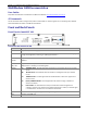
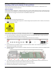
3. Use a small screwdriver to remove the six (6) screws on the back of the MultiModem iSMS. The figure that follows
uses red circles to indicate the location of these screws.
4. Lift the top cover from the back of the unit and then slide towards the front to remove.
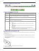
5. Insert the SIM cards into the SIM card slots on the internal wireless modems. Each modem has a graphic line
depicting the correct SIM card orientation.
6. The figure that follows uses two red boxes to indicate the location of these receptacles. Note that the SF 800 model is
used in the figure.
7. To re-attach the cover, tilt the cover up and align the “teeth” with the gaps between those on the bottom of the
chassis. The illustration uses red arrows to indicates the locations to align.
8. Rotate the cover down and push it toward the rear of the unit until it is flush.
9. Insert the six (6) screws back in to the unit and tighten.