
Datasheet


(2) Load capacitance: C
L
(C
L1
= C
L2
)
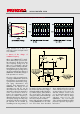
Figure 6a shows the change of oscil-
lation voltage when load capacitance
C
L
is varied. C
L
is an important para-
meter that affects the stability and fre-
quency of oscillation. Load capaci-
tance must be carefully selected to
match the IC as, when C
L
gets too
small, the wave form becomes dis-
torted (Figure 6b) and oscillation
becomes unstable. When C
L
gets too
large, the oscillation voltage decreas-
es (Figure 6c) and the oscillation may
well stop altogether.
(3) Damping resistance: Rd
Figure 7 (a) shows the change of the
oscillation voltage when damping
resistance Rd is varied. There are
many cases where an overshoot or
undershoot of oscillation voltage is
generated when the Rd is zero
(Figure 7 b). This can be avoided by
adding Rd (Figure 7 c). Also, Rd
forms a low pass filter with load
capacitance C
L2
, and mak es the
loop gain smaller at higher fre-
quency and suppresses unwanted
oscillation in the high frequency
www.murata.com
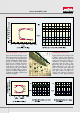
Figure 5 - Oscillation characteristics when feedback resistance R
f
is changed
Figure 6 - Oscillation characteristics when load capacitance C
L
(C
L1
= C
L2
) is changed