
Datasheet

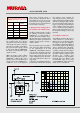

As shown in Table 1, CERALOCK
®
has a smaller value of L
1
which is
equivalent to mass M of the mecha-
nical equation of motion, and a lar-
ger value of C
1
which is equivalent to
the reciprocal of the spring constant
k. This means that the CERALOCK
®
has faster rise time than the quartz
crystal resonator.
While the quartz crystal oscillator
takes a few milliseconds to start up,
CERALOCK
®
oscillators take only a
few tens of microseconds. B ecause of
shorter start up time, CERALOCK
®
is
suitable for use in such equipment
that requires frequent start-up or
power-on from a sleep state. This is
particularly the case for microcom-
puters that use energy saving stand-
by modes, because a quick rise times
result in faster computing.
2. Design notes for selecting each cir-
cuit constant of an oscillator circuit
U sually, a C-M OS inverter is used for
an oscillator circuit that uses either
CERALOCK
®
or quartz crystal re-
sonators. H owever, as Table 1 shows,
the equivalent circuit constant values
differ very much from each other and
attention must be paid to design a
stable oscillator.
Also, the optimum circuit constant for
each component differs depending
on the combinations of IC and
CERALOCK
®
. G enerally, the optimum
value for each component is assumed
to be the circuit constant when oscil-
lation voltage at the IC’s input and
output terminals becomes the maxi-
mum value within the IC’s drive vol-
tage rating.
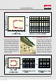
Following is an explanation of the key
points to bear in mind when selecting
the optimum circuit constants for
each component. This is demonstra-
ted by showing the oscillation voltage
and wave form (Figure 4 b) of the re-
ference circuit (Figure 4 a). Figure 4 to
Figure 6 show the peak and bottom
of the oscillation wave form, where
V
1H
, V
1L
are the measured voltages at
the IC's input terminals and V
2H
, V
2L
the measured voltages at the output
terminals.
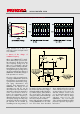
(1) Feedback resistance: R
f
The feedback resistance R
f
serves as
a bias resistance to operate the C-
M OS inverter as an inverting ampli-
fier. Figure 5a shows the changes of
the oscillation voltage when the feed-
back resistance R
f
is varied. When R
f
gets too small, the gain of the ampli-
fier decreases and consequently the
oscillation voltage decreases (Figure
5b). When R
f
gets too large, and the
insulation resistance at the IC’s input
decreases, the oscillation may
become unstable or stop altogether.
N ormally about one M ohm is the
recommended value for R
f
when
using CERALOCK
®
, if the IC has five
M ohm or more of Rf built in.
www.murata.com
Figure 4 - Ex ample of oscillator circuit and wave form
Table 1 - Typical electrical characteristics of
CERALOCK
®
and a quartz crystal resonator
CERALOCK
®
Q uartz crystal
resonator
Frequency 4 .0 0 MH z 4 .0 0 MH z
L1 (µ H ) 8 8 7 3.08 x 10
5
C1 (pF) 1.8 8 5.13 x 10
-3
C0 (pF) 15.7 1.8 3 x 10
3
R1 (Ω) 8 .04 8 .4 8