
Instruction Manual
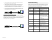
Table Of Contents

© MuxLab Inc.
3.
Plug a second balun into the each of the component video inputs (coaxial) of
the video monitor or receiver at the remote end.
4. Complete the connection between the two baluns, using standard twisted pair
cabling techniques as shown below. Each balun must be connected to its
corresponding component video balun at the other end. For example, the
component video balun for the “Y” component at the output must be connected
to the component video balun for the “Y” component at the other end.
5. Power-on the component video equipment. Check the image quality and refer
to the troubleshooting table below if the image quality is unsatisfactory. The
following diagram shows a typical installation.
Component Video Source
Component Video Baluns (500021)
Six (6) required per YPbPr connection
4-pair Cat5 twisted pair cable
DVD or VCR
Component Video Monitor
Y
Pb
Pr
Y
Pb
Pr
Composite Video (NTSC,PAL,SECAM) Connection:
One (1) pair of Component Video Baluns (two baluns) are needed to complete one
composite video connection via Cat5 twisted pair. To install the VideoEase Component
Video Baluns, perform the same steps as listed above by connecting the Component
Video Baluns to the composite video input/output connectors of the equipment. The
following diagram shows a typical installation.
Composite Video Source
Component Video Baluns (500021)
4-pair Cat5 twisted pair cable
DVD or VCR
Composite Video Monitor
Troubleshooting
The following table describes some of the symptoms, probable causes and possible
solutions in respect to the installation of the Component Video Balun. If you still
cannot diagnose the problem, please call MuxLab Customer Technical Support at
877-689-5228 (toll-free in N.Am) or 514-905-0588 (Intl).
Symptom Probable Causes Possible Solutions
No video No continuity in video
link
Verify cable continuity between
pairs of baluns.
No video Power off Check power supplies of video
equipment.
No video Improper connection
Swapped pairs
Check that baluns are connected to
correct video inputs and outputs.
Unusual colors Reversed polarity Check wiring and ensure straight-
through polarity
Background pattern EMI interference Identify possible radiating
frequency sources (ie; wireless
LANs, switching power supplies)
Try to isolate them from the video
connection.
Use shielded twisted pair grounded
at least on one end.
Smearing Exceeded distance Verify cable grade. Use higher
grade cable if necessary.
Weak contrast Exceeded distance Verify cable grade. Use higher
grade cable if necessary.
Increase contrast on monitor.
Weak contrast Unusual link attenuation Verify cable distance using
ohmmeter or cable tester.
Image not stable Defective link or
equipment
Verify video equipment interface
integrity.
Horizontal bars
moving slowly
Substantial crosstalk
between multiple video
sources
Consecutively turn off other video
sources to determine which video
source is the cause of interference.
Snowy picture Distance is near limit Verify cable grade. Use higher
grade cable if necessary.
Reduce color intensity at monitor.