
Operation Manual

04
HI-LINE RC & HI-LINE RC Heater/Cooler
5.0 Preparation
Before proceeding with the installation, unpack the carton
contents and check against the checklist below:
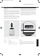
1. HI-LINE RC fan convector.
2. 15mm isolating valves (1 pair).
3. Instruction manual.
4. Warranty card.
5. Fixing kit (rubber mounts and cable gland).
6. Remote control handset.
6.0 Fixing
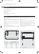
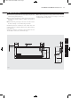
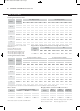
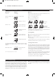
Unit A B
Dimensions (mm)
20-14 1171 1039
15-10 887 754
10-6 682 550
7-4 554 422
A
277
59
73B
94
35
49
Fig. 1
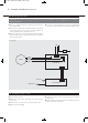
Fig. 2 Case fixing screw positions
l Using the fixing dimensions below (see fig. 1), mark the fixing
hole positions on the wall.
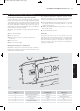
l Drill and plug the wall for No. 8 x 40mm round head wood
screws ensuring that the wall plugs are suitable for the wall
type.
l Remove the backing from two of the self-adhesive washers
and place on two of the screws with adhesive side towards
the point.
l Tighten the screws into the top two fixing holes leaving about
9mm projecting.
l Press adhesive washers to the wall.
l Remove the backing from the last self-adhesive washer and
place centrally over the bottom fixing hole on the left hand
side.
Remove the outer casing as follows:
l
Remove the 2 screws at each end of the outlet grille (see fig. 2).
l Lift off the outer case.
l Fit chassis on to the top two mounting screws and tighten.
l Secure the bottom fixing point with the remaining screw.
Note: Before proceeding with pipe-work connections check that
the unit is level. If the right hand end is lower than the left then
the ability to vent the unit may be restricted.
When water connections and electrical connections have been
completed and the unit has been vented, fit the outer cover and
secure with fixing screws.
23673 HiLine manual UK 27/06/2011 09:12 Page 5