
Operation Manual


ATTENTION!
Please make sure that the VISO THREE is powered o or unplugged from the mains power source before making any connections. It is also advisable to
power down or unplug all associated components while making or breaking any signal or AC power connections.
IDENTIFICATI ON OF CONTROLS
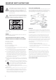
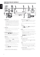
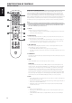
REAR PANEL
1 432 5 6 7 8 9 10
12
11
230V version only
1 SPEAKERS
The VISO THREE is designed to produce optimum sound quality when
connected to speakers with impedances within its operating range.
Please make sure that all the speakers are rated 8 ohms minimum per
speaker.
• Connect the right speaker to the terminals marked “R +” and “R-”
ensuring that the “R+” is connected to the “+” terminal on your
loudspeaker and the “R-” is connected to the loudspeaker’s “-”
terminal. Connect the terminals marked “L+” and “L-” to the left
speaker in the same way. Use extra care to ensure that no stray wires
or strands cross between posts or terminals at either end.
NOTE
Use stranded wire of at least 16 gauge (AWG). Connections to the VISO
THREE can be made with banana-type plugs, or using bare wire or pins, by
loosening the terminal’s plastic nut, making a clean, neat connection, and
re-tightening carefully. To minimize the danger of short circuit, ensure that
only 1/2-inch of exposed wire or pin is employed when connecting.
2 FM ANTENNA TERMINAL
• Connect the supplied lead-type FM antenna to the FM antenna
input. Extend the lead. Experiment freely with your antenna
placement and orientation until you get the clearest sound and
lowest background noise.
• Fix the antenna in the desired position by using thumb tacks, push
pins or any suitable means.
3 AM ANTENNA TERMINAL
The AM loop antenna supplied with the VISO THREE (or a suitable
replacement) is required for AM reception.
· Open the clip terminal lever; insert the wire making sure to match
the color-coded (white and black) ends of the wire to that of the
terminal and close the lever ensuring that the lever locks the wire in
place.
• Testing dierent positions for the antenna may improve reception;
vertical orientation will usually produce the best results. Antenna
proximity to large metal objects (appliances, radiators) may impair
reception, as will as attempts to lengthen the wire to the loop.
Refer also to the item about ASSEMBLING THE LOOP ANTENNA at the
LISTENING TO AM/FM RADIO section of the OPERATION page.
4 AUDIO 1, AUDIO 2
• Input for additional line level input signal such as another CD player
or other line level audio sources.
• Use a twin RCA-to-RCA lead to connect these sockets to the source
device’s left and right analog output.
5 MP
• Input for a Media Player or other line level audio input signal.
• Use a twin RCA-to-RCA lead to connect these sockets to the source
device’s left and right analog output.
• MP is the default port connection of the audio output of the
separately sold NAD IPD (NAD IPD Dock for iPod) 1, NAD IPD 2 or
later variant; with NAD IPD’s DATA PORT correspondingly connected
also to VISO THREE’s rear panel MP DOCK DATA PORT.
NOTE
The “NAD IPD 2 Dock for iPod” (NAD IPD 2) model is supplied with your
VISO THREE.
6 SUBW (SUBWOOFER) PRE OUT
Connect this output to a powered (active) subwoofer or to a power
amplier channel driving a passive system.
8
ENGLISH PORTUGUÊSFRANÇAIS ESPAÑOL ITALIANO DEUTSCH NEDERLANDS SVENSKA РУССКИЙ