DOWNHILL BIKER Operators Manual IT IS THE RESPONSIBILITY OF THE OPERATOR TO MAINTAIN CUSTOMER SAFETY AT ALL TIMES, AND IT IS IMPERATIVE THAT THE DETAILS SET OUT IN THIS MANUAL ARE FOLLOWED PRECISELY. Part No.
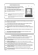
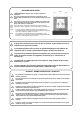
P O R TA B L E A P P L I A N C E T E S T I N G Please Note: During testing of the machine with a portable appliance tester the insulation test will show a failure due to the fitting of two VDRs between Live/Earth and Neutral/Earth. These components have been fitted to safeguard against high voltage surges that may occur on the mains supply to the machine and to comply with the EMC regulations. To conduct an insulation test on this machine, the VDRs must be isolated from the circuit first.
No part of this publication may be reproduced by any mechanical, photographic or electronic process, or in the form of phonographic recording, nor may it be stored in a retrieval system, transmitted or otherwise copied for private or public use, without permission from NAMCO EUROPE LIMITED. While the information contained in this manual is given in good faith and was accurate at the time of printing. NAMCO EUROPE LIMITED reserve the right to make changes and alterations without notice.
NOTES ON INSTALLATION NEVER turn the power to the machine ON until installation has been completed. In order to prevent possible electric shocks, be sure that the machine is connected to the mains with a securely connected earthed plug. So that customers are not injured by the movement of the machine, ensure that there is as least 500mm separation between other machines or walls. In order to avoid damage to the machine due to mis-operation, ensure that the voltage of the mains supply is 230volts AC.
쮕 Dieses Dokument darf in keiner Weise vervielfältigt werden. Jegliche Tonaufnahmen sowie die Speicherung auf Datenträger (Suchsysteme), die Weitergabe oder sonstiges Kopieren für den gewerblichen und privaten Gebrauch sind untersagt und bedürfen der vorherigen Genehmigung durch NAMCO EUROPE LIMITED. Die informationen in diesem Handbuch entsprechen den Tatsachen bei Drucklegung. NAMCO EUROPE LIMITED behält sich jedoch das Recht zu Änderungen ohne vorherige Bekanntgabe vor.
HINWEISE ZUR AUFSTELLUNG NIEMALS das Gerät einschalten bevor die Aufstellung völlig abgeschlossen ist. Zur Vermeidung von Elektroschlägen muß das Gerät mit einem ordnungsgemäß geerdetem Netzstecker an die Stromversorgung angeschlossen werden. Um zu vermeiden, daß Kunden durch die Gerätebewegungen verletzt werden, muß ein Sicherheitsabstand zu anderen Geräten und Wänden von mindestens 50cm eingehalten werden.
Denne udgivelse må ikke reproduceres af nogen som helst mekanisk, fotografisk eller elektrornisk proces eller i form af indspilning, den må heller ikke lagres i et eftersøgningssystem transmitteres eller kopieres til nogen form for offentlig benyttelse uden tilladelse fra Namco Europe Limited. Da informationerne i denne manual er givet med god tro og var korrekt på udskivningstidspunktet, forbeholder Namco Europe Limited sig retten til, at foretage ændringer og forandringer uden varsel.
PUNKTER OM INSTALLATION Tænd aldrig for strømmen til maskinen før installering er fuldført. For at undgå mulige elektriske stød sikres, at maskinen er forbundet til hovedstrømmen med sikkert monterede jordstik. For at kunder ikke kommer til skade ved spillets bevægelser sikres, at der er mindst 50cm afstand til andre maskiner og vægge. For at undgå skader på maskinen p.g.a. fejlbetjening sikres, at spændingen på hovedstrømmen er 230 volt AC.
No se permite la reproducción total ni parcial de esta publicación por ningún medio mecánico, fotográfico o electrónico, grabaciones fonográficas, ni su almacenamiento informático, su transmisión o su copia, ya sea para uso público o privado, sin permiso de NAMCO EUROPE LIMITED. Si bien la información contenida en este manual se da de buena fe y es correcta en el momento de su impresión, NAMCO EUROPE LIMITED se reserva el derecho de hacer cambios y alteraciones sin previo aviso.
NOTAS DE INSTALACIÓN. JAMÁS ENCIENDA la máquina antes de haber completado la instalación. Para evitar posibles descargas eléctricas, asegúrese de que la máquina está conectada a la red con un enchufe provisto de toma de tierra. Para que los usuarios no sufran lesiones debido al movimiento del juego, asegúrese de que hay al menos 500 mm de separación entre éste y otras máquinas o las paredes.
Aucun élément de cette publication ne sera reproduit, ni par procédé mécanique, photographique ou électronique, ni par un moyen d’enregistement phonographique. Ces informations ne seront ni stockées grâce à un procédé de récupération, ni transmises ou autrement copiées pour un usage publique ou privé, sans l’autorisation de NAMCO EUROPE LIMITED.
NOTES D’INSTALLATION NE JAMAIS mettre le jeu en marche avant que l’installation ne soit complétement effectuée. Afin de prévenir une éventuelle électrocution, s’assurer que la machine est connectée au réseau avec une prise de terre reliée selon les normes de sécurité. Afin que les clients ne soient pas blessés par les mouvements du jeu, s’assurer qu’il existe au moins 500 mm de séparation aves les autres jeux ou les murs.
ও ÊáíÝíá ìÝñïò áõôÞò ôçò Ýêäïóçò äåí ìðïñåß íá áíáðáñá÷èåß ìå ïðïéïäÞðïôå ìç÷áíéêü ,öùôïãñáöéêü Þ çëåêôñïíéêü ìÝóï , Þ ìå ìïñöÞ öùíçôéêÞò ç÷ïãñÜöçóçò êáé ïýôå íá áðïèçêåõôåß ìå åðáíïñèùôéêü óýóôçìá , íá ìåôáäïèåß Þ íá áíôéãñáöåß ãéá äçìüóéá Þ éäéùôéêÞ ÷ñÞóç , ÷ùñßò ôçí Üäåéá ôçò NAMCO EUROPE LIMITED. Êáèþò áõôÝò ïé ðëçñïöïñßåò óå áõôü ôï åã÷åéñßäéï Ý÷ïõí äïèåß ìå êáëÞ ðßóôç êáé áêñéâþò ôçí þñá ôçò ôýðùóçò , ç åôáéñåßá NAMCO EUROPE LIMITED êñáôÜåé ôï äéêáßùìá íá êÜíåé ïðïéåóäÞðïôå áëëáãÝò ÷ùñßò åéäïðïßçóç.
ÓÇÌÅÉÙÓÅÉÓ ÃÉÁ ÔÇÍ ÅÃÊÁÔÁÓÔÁÓÇ ÐÏÔÅ íá ìçí áíÜâåé ôï ìç÷Üíçìá åÜí äåí Ý÷åé ïëïêëçñùèåß ç åãêáôÜóôáóç. Ãéá ôçí áðïöõãÞ çëåêôñéêþí óïê ðñÝðåé ôï ìç÷Üíçìá íá Ý÷åé ãåéùèåß. Ãéá ôçí áðïöõãÞ êéíäýíïõ óå êÜðïéïí ðáßêôç , ðñÝðåé ôï ìç÷Üíçìá íá Ý÷åé áðüóôáóç ôïõëÜ÷éóôïí 500mm áðü Üëëï ìç÷Üíçìá Þ ôïß÷ï. Ãéá ôçí áðïöõãÞ âëÜâçò óôï ìç÷Üíçìá ëüãï ëÜèïò ëåéôïõñãßáò , ðñÝðåé ç ðáñï÷Þ íá åßíáé 230volt AC..
Nessuna parte di questa pubblicazione può essere riprodotta con processo meccanico, fotografico o lettronico, nè sotto forma di registrazione fonografica, nò può essere memorizzata in un sistema di salvataggio, trasmessa o in altro modo copiata per uso pubblico o privato, senza l’autorizzazione di NAMCO EUROPE LIMITED. Le informazioni contnute in questo manuale sono state date in buona fede ed erano accurate al momento della pubblicazione.
NOTES D’INSTALLATION NON ACCENDERE MAI la macchina finchè l’installazione non è stata completata. Allo scopo di prevenire possibili scosse elettriche, la macchina deve essere obbligatoriamente collegata alla rete con un connettore messo a terra con connessioni sicure. Perchè i clienti non siano feriti dal movimento del gioco, assicurarsi che ci siano almeno 500mm di distanza rispetto alle altre macchine o rispetto al muro.
Ingen del av denne utgivelsen må reproduseres av noen mekaniske, fotografiske elle elektroniske prosesser, eller i form av fotografiske opptak, og ikke kan det lagres i et gjenvinnbart system, sendt eler kopiert for offentlig eller privat bruk, uten tillatelse fra NAMCO EUROPE LIMITED. Da informasjonen i denne manualen er gitt i god tru og var korrekt da den ble utgitt, tillegger NAMCO EUROP LIMITED seg retten til å lage forandringer uten varsel.
MERKNADER VED INSTALLASJON Slå ALDRI på maskinens strømforsyning før installasjonen er fullført. For å forhindre eventuelle elektriske sjokk, forsikre deg om at maskinen er koplet til et strømnett med ordentlig jording. For å forhindre at kundene blir skadet av spillets bevegelige deler. forsikre deg om at det er minst 500mm avstand mellom andre maskiner eller vegger. For å forhindre skade på maskinen p.g.a. feil bruk, sørg for at spenningen til hoved strømforsyningen er 230Volt AC.
Niets uit deze publikatie mag worden gereproduceerd door enig mechanisch, fotografisch of electronisch proces, of in de vorm van een fonografische opname, noch mag het opgeslagen worden in een retrieval systeem, doorgezonden of anderszins gekopieerd voor publiek of privégebruik, zonder toestemming van Namco Europe Limited.
Opmerkingen aangaande Installatie Sluit de machine nooit aan op de stroomtoevoer totdat de installatie is voltooid. Om mogelijke electrische schokken te voorkomen, dient ervoor gezorgd te worden dat de machine middels een goed vastzittende aardstekker op het lichtnet is aangesloten. Om ervoor te zorgen dat klanten niet gewond raken door de beweging van het spel, dient ervoor gezorgd te worden dat er minimaal 500mm ruimte is tussen andere machines of muren.
Nenhuma parte desta publicacão poderá ser reproduzida por processos mecanográficos, fotográficos, electrónicos ou ainda sob a forma de gravacão sonora nem tão pouco poderá ser gravada através de sistemas informáticos transmissiveis ou de outra forma copiados para uso publico ou privado sem autorização expressa da NAMCO EUROPA LIMITADA. A informação contida neste manual foi fornecida de boa fé, sendo rigorosa na altura da sua publicação.
NOTAS SOBRE A INSTALAÇÃO NUNCA ligar a maquina sem que a instalação esteja completamente finalizada. Afim de evitar possiveis choques electricos, certifique-se que a maquina está ligada à rede de alimentação com uma ficha protegida com circuito de terra. Afim de evitar ferimentos pessoais nos clientes, provocados pelo movimento da maquina, certifique-se que existe pelo menos 500mm de separação entre outras maquinas ou paredes.
Ingen del av denna publikation får reproduceras, varken fotografiskt, elektroniskt eller i någon form av ljudinspelning. Det får inte heller lagras i något återvinningssystem, översändas eller på annat sätt kopieras för offentlig eller privat användning, utan tillstånd från NAMCO EUROPE LIMITED. Eftersom informationen i denna manual lämnas ut i god tro och var korrekt när den trycktes, reserverar sig NAMCO EUROPE LIMITED för ändringar.
ATT BEAKTA VID INSTALLATION Sätt aldrig på strömmen på maskinen innan installationen är klar. För att förhindra elektriska chocker, försäkra dig om att maskinen kopplas till strömförsörjning med jordad kontakt För att undvika skador av spelets rörelser, försäkra dig om att det finns ett avstånd på minst 500 mm till annan maskin eller vägg. För att undvika skador på maskinen p g a felaktigt handhavande, försäkra dig om att strömstyrkan är 230 volt AC.
Tästä julkaisusta ei saa ottaa missään muodossa kopioita yksityis- tai julkiseen käyttöön ilman NAMCO EUROPE LIMITED:in lupaa. Tässä ohjekirjassa olevat tiedot pitävät julkaisuhetkellä paikkansa. NAMCO EUROPE LIMITED:illä on kuitenkin oikeus muutoksiin ilman erillistä ilmoitusta. Tämä laite on valmistettu EC direktiivien mukaisesti. Se on testattu ja todettu noudattavan seuraavia direktiivejä: 89/336/EEC ja 72/23/EEC (EN55014, EN55104 ja EN 60335-1 standardit).
ASENNUSHUOMIOITA Älä koskaan kytke laitetta päälle ennen kuin asennus on suoritettu loppuun. Tämän laitteen virtalähde on kytkettävä maadoitetulla johdolla maadoitettuun pistorasiaan, jotta sähköiskun vaaraa ei olisi. Varmista, että laitteen ja seinän tai toisen laitteen välissä on vähintään 500 mm, jotta asiakkaat eivät loukkaannu laitteen likkumisesta johtuen. Varmista, että virtalähteen jännite on 230 V AC, jotta ei laite vioitu. Huomio: Jos tämä laite sijoitetaan liukkaalle esim.
1. SPECIFICATIONS POWER SUPPLY:- 230volts / 400watts A.C. AMBIENT OPERATING TEMPERATURE: +5°C to +25°C MONITOR:- Hantarex 28” Polo (auto degauss) COIN ACCEPTOR:- Mars CashFlow 4 Channel - Dispense DIMENSIONS:Assembled 1800(w) x 2040(d) x 2090(h) 1790(w) x 690(d) 800(w) x 1350(d) 1610(w) x 320(d) x 1680(h) x 1200(h) z 550(h) Monitor Cabinet Bike Assembly Header Assembly WEIGHT:Assembled 605kg Monitor Cabinet Bike Assembly Header Assembly 245kg 165kg 20kg ACCESSORIES:- Keys: (Cash Door) .
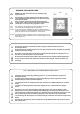
2. HOW TO PLAY This game simulates downhill racing using a mountain bike. Up to four players, (if two games are linked), can play at the same time. At the start of the game each player selects one of four characters and a racing course, (Speed course or Technical course). Both pedalling and steering techniques are required to win the game. (1) Control The player controls the bike like an ordinary mountain bike. Use the pedals to go forward, operate the handle to steer, and brake to decelerate.
3.
4. MOVING THE MACHINE This machine is fitted with castors to make it easier to move. Take care when moving the machine on an inclined surface. The overall height of the machine is 2090mm. Take care of any overhead obstructions. (e.g. Light Fittings, Electric Cables etc.) When moving the game, ensure that the game is disassembled into 3 parts: Monitor Assembly, Ride Assembly, and Header Assembly. 5.
1. 2. 3. 4. 5. 6. 쮕 1. 2. 3. 4. 5. 1. 2. 3. 4. 5. 1. 2. 3. 4. 5. This machine is designed for INDOOR USE ONLY. Do not install in the following places. Outdoors Direct Sunlight, places with excessive humidity or dust, places where there is water leakage, near air-conditioning or heating equipment, places with excessive heat or cold temperature. Places where it would be in the way of emergency exits or fire extinguishing equipment. Unstable places or places with excessive vibration.
1. 2. 3. 4. 5. ও 1. 2. 3. 4 5. 1. 2. 3. 4. 5. 1. 2. 3. 4. 5. 1. 2. 3. 4. 5. CETTE MACHINE EST DESTINEE UNIQUEMENT A UN USAGE INTERIEUR NE PAS INSTALLER LA MACHINE DANS LES ENDROITS SUIVANTS A l’extérieur. Directement exposée au soleil, aux endroits excessivement humides ou poussiéreux, aux endroits où il y a des risques de fuite d’eau, près de ventilateurs ou source de chaleur, aux endroits très chauds ou froids.
1. 2. 3. 4. 5. 1. 2. 3. 4. 5. 1. 2. 3. 4. 5. ESTA MAQUINA FOI CONCEBIDA PARA UTILIZAÇÃO EM ESPACOS INTERIORES APENAS NÃO INSTALAR A MAQUINAS NOS SEGUINTES LOCAIS:Exteriores. `Luz solar directa, locais com humidade excessiva ou pó, locais aonde existam fugas de água perto de ar condicionados ou equipamentos calorificos e locais com temperaturas excessivamente quentes ou frias. Locais aonde ficaria colocada no caminho de saidas de emergência ou equipamentos extintores de fogo.
5-1 Fitting the Header Assembly The Header Assembly has a forward centre of gravity, so it is important that at least two people are used to fit or remove the Header Assembly. The fitting position of the Header Assembly is very high, and it is important that a means of reaching the height safely, without stretching, is available. (e.g. steps, step stool etc.) 1. Place the header assembly on to the monitor cabinet and connect the connector. 2.
5-2 Fitting the Bike Assy 1. Remove the 4off socket head screws (M8x16), remove the shipping bracket and rubber pad from each bike, and refit the 4off hex head screws (M8x16). 2. Remove the 2off security screw (M5x12) and remove the roping bracket and protective paper on the rear of each bike. Refit the 2off security screws (M5x12) 3. Place the bikes close to the monitor cabinet and connect the connectors.
4. Fit the joint brackets using 4off hex head screws (M8x20). 5. Slacken the 4off hex head screws (M8x20) on the inner side of each bike so that there is approximately 10mm of thread showing. 6. Remove 4off security screw (M5x12) and remove the cover and end bracket from the joint box.
7. Fit the joint box between the two bikes so that the slots on the side of the joint box fit over the hex head screws (M8x20). 8. Tighten the hex head screws to retain the joint box. 9. Place the shipping brackets, rubber pads, roping brackets and protective papers previously removed into the joint box for future use. 10. Refit the joint box cover and end bracket with the 4off security screws (M5x12).
11. Fit the connector cover using the 2off security screw (M5x12). 12. When the machine is in its final position, lower the fourteen level adjusters, (6 on the monitor cabinet and 4 on each ride assy), with a spanner so that the machine is level and all castors are raised from the floor by approx. 5mm. Tighten the lock nuts with a spanner to ensure that the level adjusters do not move.
5-3 Fitting the Number Decals When the game has been assembled, fit the number decals to the monitor cabinet and each bike. The number decals should be fitted in ascending order from the left. 1 GAME - 2 PLAYERS 2 GAMES - 4 PLAYERS Ensure that the PCB ID is set to match the decal number. (Refer to Section 6-3-2 Page 48 for PCB ID setting.) Failure to do so may cause the game to operate incorrectly.
5-4 Linking Games A single game (2 players) is linked using two short link cables as shown below. To link two games (4 players):1. Remove 2off pozi head screws (M4x12) and remove the link cover bracket. 2. Using the longer link cables (supplied) link the two games as shown below. 3. Refit the link cover bracket with the 2off pozi head screws (M4x12). Note:- Retain the removed short link cables safely for future use.
If there is a failure of one game PCB, fit the link cables as shown below to isolate the faulty unit and allow the other PCB(s) to operate correctly.
6. ADJUSTMENTS 쮕 Adjustment or maintenance on this machine should be carried out by qualified personnel only. Aufstellung, Service, Einstellung und Wartung dürfen nur von dafür qualifiziertem Fachpersonal durchgeführt werden. eller vedligehold af denne maskine bør kun udføres af Justeringer kvalificeret personale. ও Los ajustes y el mantenimiento de esta máquina deben ser realizados sólo por personal cualificado.
6-2 Adjustment Switches The Adjustment switches are located inside the coin door. 1. Service Switch. Press this switch to obtain game credits without incrementing the play meter. 2. Test Switch Slide the test switch ON to enter test mode. Test mode allows testing and the changing of game settings. (Refer to section 6-3 "Test Mode" page 46) 3. Select Up/Down Switch This switch is used to select the test required when in the Test Mode. 4.
6-3 Test Mode 1. Open the coin door and slide the test switch “ON”. The “Menu Screen” will be displayed on the monitor. 2. Select the test required by using the select up/down switch. The colour of the selected test will change. 3. Activate the test by pressing the Enter switch. Select “EXIT” in each test to return to the “Menu Screen”. 4. After testing is completed, slide the test switch to the “OFF” position to return to normal game mode.
6-3-1 Coin Options 1. Select “COIN OPTIONS” on the menu screen to set the game cost and related settings. The following screen is displayed. 2. Use the Select Up/Down switch to choose the required item then press the Enter button. 3. Use the Up/Down switch to change the setting. 4. Select “EXIT” and press the Enter button to return to the menu screen. Note:- The price of play on this machine is set within the Cashflow Coin Mech. Ensure that the Game Cost is set to 1 Coin 1 Credit.
6-3-2 Game Options 1. Select “GAME OPTIONS” on the menu screen to set the game variables. The following screen is displayed. 2. Use the Select Up/Down switch to choose the required item then press the Enter button. 3. Use the Up/Down switch to change the setting. 4. Select “EXIT” and press the Enter button to return to the menu screen. GAME OPTIONS PCB ID 1 .................................. (a) ENTRY WAIT 14 .................................. (b) ATTRACT SOUND ON ....
6-3-3 I/O Test 1. Select “I/O TEST” on the menu screen to switches and lamps. The following screen is displayed. 2. Use the Select Up/Down switch to choose the required item then press the Enter button to enter the test. 3. Select “EXIT” and press the Enter button to return to the menu screen. I/O TEST DIP 4 12345678 [ON:RED] .............................................. (a) LINK ON 2 ............................................ (b) I/O PCB CHECK ............................................
6-3-3-1 I/O PCB Check 1. Select ‘I/O PCB CHECK’ from the I/O Test Screen. The following screen is displayed:- I/O TEST DIP 4 12345678 [ON:RED] LINK ON 2 I/O PCB CHECK Master TX 3536 NAMCO LTD. DOWNHILL BIKERS ; Ver1.00 ; JPN 1/0 PCB CONNECT OK NAMCO LTD. ASCA-4 EXIT SELECT SW : CHOOSE ENTER SW : ENTER 6-3-3-2 How to [I/F Initialize] 1. Select ‘I/O PCB CHECK’ from the I/O Test Screen.
6-3-3-3 Switch Test 1. Select “Switch Test” on the I/O menu screen to test the switches. The following screen is displayed. 2. The display shows the current state of the switches. 3. Press the Up Select switch and the Enter switch together to EXIT and return to the I/O menu screen SWITCH TEST DIP 4 123456787 [ON/OFF] LINK ON 2 SWITCH TEST COIN SERVICE TEST UP SELECT DOWN SELECT ENTER BUTTON BRAKE RIGHT BRAKE LEFT PEDAL ENCODER HANDLE BAR 000 ................................. OFF ......................
6-3-3-4 Pedal & Lamp Test 1. Select ‘I/O PCB CHECK’ from the I/O Test Screen. The following screen is displayed:- I/O TEST DIP 4 12345678 [ON:RED] LINK ON 2 PEDAL & LAMP TEST PEDAL BRAKE 0 1 2 3 4 OFF MIN >>> >>> MAX BUTTON LAMP ON (a) .........................................................
6-3-4 Monitor Test 1. Select “MONITOR TEST” on the menu screen to test and adjust the Monitor. The following screen is displayed. 2. Use the Select Up/Down switch to choose the required item then press the Enter button. To return to the Monitor Test Menu from a test pattern press the Enter button. 3. Select “EXIT” and press the Enter button to return to the menu screen.
6-3-5 Sound Test 1. Select “I/O TEST” on the menu screen to switches and lamps. The following screen is displayed. 2. Use the Select Up/Down switch to choose the required item then press the Enter button. 3. Use the Up/Down switch to change the setting. 4. Select “EXIT” and press the Enter button to return to the menu screen. SOUND TEST VOLUME FRONT L SP FRONT R SP (0~64) (0~64) REQUEST SONG NO. MESSAGE 40 .................................... 40 ...............................
6-3-6 ADS Data By selecting ADS Data from the menu screen, all of the bookkeeping details can be read and/or reset. 6-3-7 Others 1. Select “OTHERS” on the menu screen. The following screen is displayed. 2. Use the Select Up/Down switch choose the required item then press the Enter button. 3. Select “EXIT” and press the Enter button to return to the menu screen. OTHERS ROM1 Ver. ROM2 Ver. 97/07/07 97/06/27 MON FRI 21:15:59 20:11:35 ....................(a) CLOCK 97/08/27 WED 23:11:12 .........
7, INITIALIZATION Adjustments when Replacing Parts (Initialization) The following adjustments should always be performed after replacing the Game PC Board, ROM, or Control Potentiometers. The game will not operate correctly if these adjustments are not made. Note: After initialization perform “SWITCH TEST” (see section 6-3-3-3 page 51) and make sure “RIGHT OK” and “LEFT OK” is displayed when the handle bar is turned fully right and left. 1. Slide the TEST switch ON while pressing the SERVICE Switch.
8. MAINTENANCE NOTE: 12 weeks after purchase, increase the torque of the crank nut to 450kgf/cm. (refer to section 8-6 (6)) 8-1 Daily Check 1. Pedal the machine, and ensure that the pedals rotate smoothly. 2. Hold one of the pedals and check that the other peddle has no wobble. 3. Check that there is no movement along the pedal shaft. 4. If any shaft movement is found, tighten the pedal or crank.
8-2 Replacing the Monitor The monitor is heavy. At least two people are required to remove the monitor. 1. Disconnect the bike assembly from the monitor cabinet first (see section 5-2 page 37), to allow a safe and sufficient space to work 2. Remove the 2off upper security screw (M5x12) and slacken the 2off lower security screw (M5x12), and remove the monitor rear access panel. 3. Remove the pozi head screw (M4x10) and remove the Earth wire and connectors from the monitor. 4.
5. Remove 17off security screw (M5x16) and remove the monitor vac-form and speaker grille. 6. Remove 4off pozi head screws (M5x20) with flat and spring washer and remove the front support rail.
7. Remove 4off pozi head screw (M8x25) and flat washer, and remove the monitor by tilting the top forward and lifting the monitor out. Note:- Take care not to knock the neck of the monitor tube when handling as it can be easily damaged and the tube destroyed.
8-3 Replacing the Fluorescent Tube or Starter 1. Remove 4off security screw (M5x16) and remove the top retaining bracket and header acrylic. 2. Replace the fluorescent tube or starter. 3. Refit the header acrylic and top retaining bracket.
8-4 Replacing the Bike Potentiometer 1. Remove 3off security screw (M5x16) and remove the rear vac-form. 2. Disconnect the connector. 3. Slacken the grub screw (M4x6) and remove the potentiometer complete with bracket. 4. Replace the potentiometer taking care to connect the correct colour wire to the correct terminal. When replacing the potentiometer ensure that the locating tab on the potentiometer engages in the hole in the mounting bracket. 5.
8-5 Replacing the Pedals 1. Remove the pedals by using an allen key fitted to the inner end of the pedal shaft, and turning the allen key, when pointing up, to the rear of the bike. (i.e. the left hand pedal has a left hand thread.) When replacing the pedals, ensure that the correct pedal is used. The pedals have L or R stamped on them. 8-6 Replacing the Crank Arms A two part tool is supplied to enable the fitting and removal of the crank arms. Ensure that this tool is kept with the machine at all times.
4. Screw end A into the crank shaft and using a spanner, screw end B clockwise to remove the crank arm. 5. To refit the crank arm, place the crank arm onto the pedal shaft, enuring that the correct crank arm is being fitted. 6. Fit the crank nut, and fully tighten using end B of the special tool. 7. Refit the plastic end cap.
8-7 Adjusting the Belt 1. Remove both left and right crank arms complete with pedals. (See section 8-6 page 35) 2. Remove 10off security screw (M5x16) and 4off security screw (M5x20), and remove both side vac-forms. 8-8 Adjusting the Chain 1. Remove the pedals and crank arms. (see section 8-6 page 63) 2. Remove the side vac-forms. (see section 8-7 above) 3. Loosen 4off flanged socket head screws (M6x14) and 2off nuts (M8) of the work load unit. (Do not remove the screws or nuts). 4.
5. Retighten the flanged socket head screws and nuts. 6. Refit the side vac-forms and pedals. 8-9 Replacing the Chain 1. Remove the pedals and crank arms. (see section 8-6 page 63) 2. Remove the side vac-forms. (see section 8-7 page 65) 3. Disengage the chain by turning the chain wheel in the direction of arrow 2 while pulling the chain toward you (in the direction of arrow 1). 4. Engage the chain with the chain wheel of the work load unit and between the pedal chain wheel and sensor sprocket.
8-10 Replacing the Sensor PCB 1. Remove the pedals and crank arms. (see section 8-6 page 63) 2. Remove the side vac-forms. (see section 8-7 page 65) 3. Remove 2off pozi head screw (M4x8) and remove the sensor PCB cover, and disconnect the connector. 4. Remove 2off pozi head screw (M4x8) and remove the sensor PCB. 8-11 Replacing the Sensor Assembly 1. Remove the pedals and crank arms. (see section 8-6 page 63) 2. Remove the side vac-forms. (see section 8-7 page 65) 3.
Refitting the Sensor Assy 1. Refit the sensor assembly and fit loosely with two 2off flanged socket head bolts (M6x14). 2. Adjust the position of the sensor assembly so that the 10T sprocket of the sensor assembly is in line with the chain and not moving the chain to one side.. 3. Tighten fully the 2off flanged socket head bolts (M6x14). 4. Refit the side vac-forms and pedals.
8-12 Replacing the Saddle 1. Remove the pedals and crank arms. (see section 8-6 page 63) 2. Remove the side vac-forms. (see section 8-7 page 65) 3. Remove the socket cap screw (M8x25) and remove the saddle and stem. 4. Remove 2off socket cap screws (M8x35) and remove the saddle from the stem. 5. Replace the saddle and reassemble in reverse order.
8-13 Replacing the Brake Switch 1. Remove 2off security screw (M5x16) and remove the handle cover vacform. 2. Remove 2off pozi head screws (M2x10) and remove the microswitch sufficiently to remove the wires from the switch terminals. 3. Replace the microswitch. 4. Reassemble in reverse order.
10.
Item Description Part No 1 Header Vac-Form (LHS) 46000802 2 Header Vac-Form Decal Set (LHS) 40000141 3 Header Acrylic 30000000 4 Header Acrylic Top Securing Bracket 46000804 5 4’ Fluorescent Fitting - complete 64000045 6 4’ Fluorescent Tube 6 4500039 7 Header Vac-Form (RHS) 46000801 8 Header Vac-Form Decal Set (RHS) 40000140 Page 72
Item Description Part No 1 Transit EI PCB XXF-TRANSIT2PCB 2 Interlock Switch Cover 39000028 3 Interlock Switch 60000006 4 Link Cover Bracket 46000798 5 20mm Panel Mount Fuse Holder 63500786 6 Fuse - 500mA 20mm Q/B 63500608 7 Schaffner Mains Input Assembly 62500010 8 Schaffner Boot 66000017 Page 73
Item Description Part No 1 Switchmode Power Supply 5v/30A 83000001 2 3.3v Converter PCB Assembly 83000002 3 3.
Item 1 Description Part No 3.
Item Description Part No 1 Front Centre Cover 46000757 2 Front Cover - RHS 46000756 3 Front Cover - LHS 46000755 5 Warning Decal 40000466 6 Front Top Cover - LHS/RHS 46000759 7 Chequer Plate Flooring - LHS/RHS 46000760 8 Mounting Bracket A 46000758 Front Tower Decal - LHS 40000110 Front Tower Decal - RHS 40000108 11 Fork Here Decal 40000072 12 Swivel Castor 75mm 59000005 13 Adjustable Foot M20 x 100 Anti Slip w/Nut 25000001 10 Page 76
Item Description Part No 1 Plastic End Cap XDB-677-905 2 Crank Nut XDB-677-904 3 P edal XDB-677-906 4 Right Crank XDB-677-902 5 Side Vac-Form (R) XDB-677-648 6 Punched Cover XDB-677-652 7 Harness Pipe XDB-677-622 8 Rear Slide Plate XDB-677-647 9 Spring Inner Support XDB-677-665 10 Saddle 46000764 11 Saddle Clamp 46000765 12 Saddle Base 46000763 13 Side Vac-Form (L) XDB-677-649 14 Left Crank XDB-677-903 Page 77
Page 78
Item Description Part No 1 Racing Base Label (L and R) and Frame Label (a set) XDB-677-521 2 Back Cover XDB-677-642 3 Frame Base Cover XDB-677-651 4 Pillow Cover XDB-677-641 5 Holder Label XDB677-664 6 Holder XDB-677-653 7 Ride Stopper XDB-677-646 8 Potentiometer 40‡ XDB-008-021 9 Potentiometer Control Bracket XDB-677-644 10 Washer D45d15 XDB-677-645 11 Pillow Block - UCPE207 XDB-103-090 12 Pillow Block - UCPE203 XDB-103-091 13 Washer B XDB-450-132 14 Roster Bracke
Page 80
Item Description Part No 1 Handle Cap XDB-677-639 2 Washer B XDB-450-132 3 Fork Joint XDB-677-631 4 Fork Cover XDB-677-650 5 Cable Tie XDB-677-908 6 Parallel Key - 8 x 7 x 70 XDB-107-070 7 Ride Stopper XDB-677-646 8 Front fork XDB-677-632 9 Washer - D24d9 XDB-677-637 10 Link Plate XDB-677-633 11 Rod end XDB-107-069 12 Link Bushing XDB-677-635 13 Rod End Cover XDB-677-636 14 Link Arm XDB-677-634 15 Ride Frame XDB-677-611 Page 81
Item D escri pti on Part No 1 Sensor Uni t Assembly ----------- 2 Adjusti ng Bracket XD B-677-623 3 Idler Spri ng XD B-677-913 4 Idler Set XD B-677-911 5 D elayer Set XD B-677-912 6 C hai n XD B-677-915 7 Fi xi ng Bolt and Nut XD B-677-901 8 Sprocket XD B-677-900 9 C rank Shaft XD B-677-630 10 Si ngle Groove Ball Beari ng XD B-103-083 11 Beari ng Bush XD B-677-626 12 C rank Washer XD B-677-629 13 C rank Nut - L XD B-677-627 14 C rank Nut - S XD B-677-628 15 D el
Item Description Part No 1 Sensor PCB Cover XDB-677-662 2 P edal P C B XDB-637-062 3 Sensor Shaft XDB-677-914 4 Single Groove Ball Bearing XDB-103-089 5 Sensor Bushing XDB-677-663 6 Oil-less Bushing XDB-104-004 7 Sensor Guide XDB-677-615 8 Sensor Unit XDB-677-615 9 Sensor Cover XDB-677-619 10 Sensor Washer XDB-677-620 11 Sensor Stopper XDB-677-666 12 Sensor Label XDB-637-163 13 Sensor Board XDB-677-618 14 Sensor Guide Cover XDB-677-616 Page 83
Page 84
Item Description Part No Control Box Cover Vac-Form - RHS 46000775 Control Box Cover Vac-Form - LHS 46000776 Microswitch - SSG-5L3T 60000094 Lever Spring A - (LHS) 46000778 Lever Spring B - (RHS) 46000645 4 Baneate Washer 46000642 5 Oilite Bush LFF-1015 46000779 Control Box Plate - RHS 46000775 Control Box Plate - LHS 46000776 7 Lever Spring Actuator Shaft 46 000768 8 Accelerator/Brake Lever Pin 46000767 9 Accelerator Lever 46000076 10 Control Box Stud Spacer 46000769 11
11.
Page 87