INSTALLER: THESE INSTRUCTIONS MUST BE CONVEYED TO AND REMAIN WITH THE HOMEOWNER. CERTIFIED UNDER CANADIAN AND AMERICAN NATIONAL STANDARDS, CSA 2.33, ANSI Z21.
TABLE of CONTENTS PG 2-5 23-24 INTRODUCTION 5-15 VENTING Venting Lengths Air Terminal Locations Typical Vent Installations Special Vent Installations Venting Application Flow Chart Venting Specifications Pre-Installation Preparation 16-22 FINISHING Door Removal & Installation Louvre Removal & Installation Log Placement Charcoal Embers Vermiculite Glowing Embers Logo Placement Warranty General Instructions General Information Care of Glass & Plated Parts Specifications 25 26 27-28 OPTIONAL BLOWER
NAPOLEON gas fireplaces are manufactured under the strict Standard of the world recognized ISO 9001 : 2000 Quality Assurance Certificate. NAPOLEON products are designed with superior components and materials, assembled by trained craftsmen who take great pride in their work. The burner and valve assembly are leak and test-fired at a quality test station.
GENERAL INSTRUCTIONS THIS GAS FIREPLACE SHOULD BE INSTALLED AND SERVICED BY A QUALIFIED INSTALLER to conform with local codes. Installation practices vary from region to region and it is important to know the specifics that apply to your area, for example: in Massachusetts State: • The fireplace damper must be removed or welded in the open position prior to installation of a fireplace insert or gas log. • The appliance off valve must be a “T” handle gas cock.
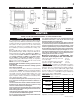
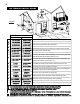
GD36 SPECIFICATIONS BGD36 SPECIFICATIONS FIGURE 1a FIGURE 1b VENTING MODELS GD36 AND BGD36 MAY BE VENTED EITHER AS A TOP VENT OR A REAR VENT. REFER TO THE SECTION APPLICABLE TO YOUR INSTALLATION. VENTING LENGTHS Use only Wolf Steel or Simpson Dura-Vent Model DV-GS venting components. Minimum and maximum vent lengths, for both horizontal and vertical installations, and air terminal locations for either system are set out in this manual and must be adhered to.
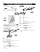
AIR TERMINAL INSTALLATIONS FIGURE 2 INSTALLATIONS CANADIAN U.S.A. A 12 INCHES 12 INCHES B 12 INCHES 9 INCHES C 12 INCHES* 12 INCHES* D 18 INCHES** Vertical clearance to ventilated soffit located above the terminal within 18 INCHES** a horizontal distance of 2 feet from the centerline of the terminal. E 12 INCHES** 12 INCHES** Clearance to unventilated soffit.
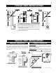
TYPICAL VENT INSTALLATIONS REAR EXIT TOP EXIT FIGURES 3a-d * For optimum performance, it is recommended that all horizontal runs have a 1 inch rise per foot. When terminating vertically, the vertical rise is a minimum 36 inches and a maximum 40 feet from the centre of the fireplace flue outlet. * When using rigid venting, this minimum vertical length may be reduced to 8½".
W415-0210 / E / 06.25.03 horizontal run + vertical rise to maximum of 40 feet horizontal run + vertical rise to maximum of 24.75 feet horizontal run + vertical rise to maximum of 40 feet 3.
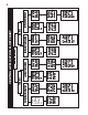
DEFINITIONS for the following symbols used in the venting calculations and examples are: > - greater than > - equal to or greater than < - less than < - equal to or less than HT - total of both horizontal vent lengths (HR) and offsets (HO) in feet HR - combined horizontal vent lengths in feet HO - offset factor: .03(total degrees of offset - 90°*) in feet VT - combined vertical vent lengths in feet ELBOW VENT LENGTH VALUES feet 0.03 0.45 0.9 1.35 2.7 1° 15° 30° 45° 90°* inches 0.5 6.0 11.0 16.0 32.
TOP EXIT / HORIZONTAL TERMINATION when (HT) > (VT) Simple venting configuration (only one 90° elbow) Example 3: 90° H1 FIGURE 8 See graph to determine the required vertical rise VT for the required horizontal run HT. V1 90° V2 H2 H4 H3 FIGURE 10 REQUIRED VERTICAL RISE IN INCHES VT HORIZONTAL VENT RUN PLUS OFFSET IN FEET HT The shaded area within the lines represents acceptable values for HT and VT .
REAR EXIT / HORIZONTAL TERMINATION when (HT) < (VT) Example 4: Simple venting configuration (only two 90° elbows) 90° H3 90° V2 H2 90° FIGURE 12 V1 FIGURE 11 H1 90° See graph to determine the required vertical rise VT for the required horizontal run HT REQUIRED VERTICAL RISE IN FEET VT HORIZONTAL VENT RUN PLUS OFFSETS IN FEET HT The shaded area within the lines represents acceptable values for HT and VT .
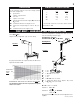
REAR EXIT / HORIZONTAL TERMINATION when (HT) > (VT) Example 5: Simple venting configuration (only two 90° elbows) 90° H4 90° V2 FIGURE 13 H2 45° 90° H3 V1 H1 90° FIGURE 14 See graph to determine the required vertical rise VT for the required horizontal run HT REQUIRED VERTICAL RISE IN INCHES VT V1 V2 VT H1 H2 H3 H4 HR HO HT H T + VT HORIZONTAL VENT RUN PLUS OFFSETS IN FEET HT The shaded area within the lines represents acceptable values for HT and VT .
TOP OR REAR EXIT VERTICAL TERMINATION when (HT) < (VT) Example 6: Simple venting configurations FIGURE 15 V2 FIGURE 16 90° H2 H1 90° V1 90° See graph to determine the required vertical rise VT for the required horizontal run HT. REQUIRED VERTICAL RISE IN FEET VT V1 V2 = 5 ft = 10 ft VT H1 H2 HR HO = V1 + V2 = 5 + 10 = 15 ft = 3 ft = 2.5 ft = H1 + H2 = 3 + 2.5 = 5.5 ft = .03(three 90° elbows - 90°) = .03(90 + 90 + 90 - 90) = 5.4 ft = HR + HO = 5.5 + 5.4 = 10.9 ft = 10.9 + 15 = 25.
TOP OR REAR EXIT VERTICAL TERMINATION when (HT) > (VT) Simple venting configurations V1 V2 V3 FIGURE 17 = 2 ft = 1 ft = 1.5 ft VT H1 H2 HR HO = V1 + V2 + V3 = 2 + 1 + 1.5 = 4.5 ft = 6 ft = 2 ft = H1 + H2 = 6 + 2 = 8 ft = .03(four 90° elbows - 90°) = .03(90 + 90 + 90 + 90 - 90) = 8.1 ft HT = HR + HO = 8 + 8.1 = 16.1 ft HT + VT = 16.1 + 4.5 = 20.6 ft HT < 3VT 3VT = 3 x 4.5 = 13.5 ft 16.1 > 13.5 Since this formula is not met, this vent configuration is unacceptable. Formula 2: HT + VT < 40 feet 20.
PRE-INSTALLATION PREPARATION FAILURE TO INSTALL THE CAP WILL CAUSE THE FIREPLACE TO FUNCTION IMPROPERLY AND CAN CAUSE INJURY OR PROPERTY DAMAGE. SEE TOP EXIT PREPARATION FOR DETAILS. For optimum performance, it is recommended that all horizontal runs have a 1 inch rise per foot. REAR EXIT: TOP EXIT: Remove the baffle from the back of the firebox (Model GD36 only) by removing the four screws. FIGURE 20. Remove the baffle from the back of the firebox (Model GD36 only) by removing the four screws.
INSTALLATION WALL AND CEILING PROTECTION FOLLOW THE VENTING INSTRUCTIONS EXACTLY. NOTE: REAR EXIT - A clearance to combustibles of 1" at the bottom of the vent and 2" at the top must be maintained during the first 12" of venting when penetrating combustible walls. The firestop spacer (W615-0044) supplied with the unit should be used to maintain this clearance. Thereafter a 1" clearance to combustibles may be maintained using firestop spacer (W500-0096).
USING FLEXIBLE VENT COMPONENTS Use only approved aluminum flexible liner kits marked: "Wolf Steel Approved Venting" as identified by the stamp only on the 7” outer liner. For safe and proper operation of the fireplace, follow the venting instructions exactly. HORIZONTAL AIR TERMINAL INSTALLATION 1. Cut or frame a hole in an exterior wall with a minimum round or square opening of 10½ inches. Secure the firestop spacer over the opening to the interior wall. 2.
5. Remove nails from the shingles, above and to the sides of the chimney. Place the flashing over the air terminal and slide it underneath the sides and upper edge of the shingles. Ensure that the air terminal is properly centred within the flashing, giving a 3/4" margin all around. Fasten to the roof. Do not nail through the lower portion of the flashing. Make weather-tight by sealing with caulking. Where possible, cover the sides and top edges of the flashing with roofing material. 6.
VERTICAL VENTING INSTALLATION Before attaching elbows to the collars on the back of the fireplace, 1½" will need to be trimmed off the 4" collar. REAR VENT APPLICATION: Attach 4" and 7" elbows to the fireplace. Secure with 3 screws and seal the joints and screw heads using high temperature sealant. Proceed to step 1 below. TOP VENT APPLICATION: 1. Move the fireplace into position. 2. Fasten the roof support to the roof using the screws provided. FIGURE 30. The roof support is optional.
GAS INSTALLATION MOBILE HOME INSTALLATION Proceed once the vent installation is complete. 1. Move the fireplace into position and secure using the nailing tabs and/or secure to the floor through the ¼"ø holes located at either end of the base. 2. Route a 3/8" N.P.T. black iron gas line, 1/2" type-L copper tubing or equivalent to the fireplace. 3. For ease of accessibility, an optional remote wall switch or millivolt thermostat may be installed in a convenient location.
BGD36 FIGURE 39a-d GD36 FIGURE 40a-d W415-0210 / E / 06.25.
MANTLE CLEARANCES FIGURES 43a-c Combustible mantle clearance can vary according to the mantle depth.Use the graph to help evaluate the clearance needed. Curtains, above the fireplace, must not be positioned lower than the 2" distance required for the 2" combustible mantle. These same requirements apply to any combustibles protruding on either side of the fireplace.
FINISHING DOOR REMOVAL & INSTALLATION FLANGE HOOD DOOR OPENING AND CLOSING: The upper louvres must be removed to allow the door to be opened or closed. To access the lower door latch, open the UPPERLOUVRE valve control door. Release the top and bottom door latches, located at the right DOOR LATCH a FIGURE 44a-d side of the door.
LOG PLACEMENT TM PHAZER logs and glowing embers exclusive to Napoleon Fireplaces, provide a unique and realistic glowing effect that is different in every installation. Take the time to carefully position the glowing embers for a maximum glowing effect. Log colours may vary. During the initial use of the fireplace, the colours will become more uniform as colour pigments burn in during the heat activated curing process. FIGURE 46a-d #5 4.
OPTIONAL BLOWER INSTALLATION red k blac I N S TA L L A TION TO BE DONE BY A QUALIFIED INSTALLER and must white be electrically connected and grounded in accordance with local codes. In the abFIGURE 48 sence of local codes, use the current CSA C22.1 CANADIAN ELECTRICAL CODE in Canada or the ANSI/NFPA 70 NATIONAL ELECTRICAL CODE in the United States If the fireplace was not previously equipped with a blower: route a grounded 2-wire, 60hz power cable to the receptacle / junction box.
OPTIONAL FAN INSTALLATION ELECTRICAL INSTALLATION TO BE DONE BY A QUALIFIED INSTALLER and must be connected and grounded in accordance with local codes. In the absence of local codes, use the current CSA C22.1 CANADIAN ELECTRICAL CODE in Canada or the ANSI/NFPA 70 NATIONAL ELECTRICAL CODE in the United States. OPTIONAL THERMOSTATIC SENSOR RECEPTACLE / JUNCTION BOX VARIABLE SPEED/ PIEZO IGNITOR BRACKET OPEN ENDED SLOTS To safely install the fan, turn off the electricity first.
OPERATION / MAINTENANCE Purge all gas lines with the glass door of the fireplace removed. Assure that a continuous gas flow is at the burner before installing the door. When lit for the first time, the fireplace will emit a slight odour for a few hours. This is a normal temporary condition caused by the curing of the logs and the "burn-in" of internal paints and lubricants used in the manufacturing process and will not occur again.
MAINTENANCE TURN OFF THE GAS AND ELECTRICAL POWER BEFORE SERVICING THE FIREPLACE. CAUTION: Label all wires prior to disconnection when servicing controls. Wiring errors can cause improper and dangerous operation. Verify proper operation after servicing. This fireplace and its venting system should be inspected before use and at least annually by a qualified service person. The fireplace area must be kept clear and free of combustible materials, gasoline or other flammable vapours and liquids.
REPLACEMENTS Contact your dealer or the factory for questions concerning prices and policies on replacement parts. Normally all parts can be ordered through your Napoleon dealer or distributor. * WARNING: This is a fast acting thermocouple. It is an integral safety component. Replace only with a fast acting thermocouple supplied by Wolf Steel Ltd. When ordering replacement parts always give the following information: 1. MODEL & SERIAL NUMBER OF FIREPLACE 2. INSTALLATION DATE OF FIREPLACE 3.
W415-0210 / E / 06.25.
TROUBLE SHOOTING GUIDE BEFORE ATTEMPTING TO TROUBLESHOOT, PURGE YOUR UNIT AND INITIALLY LIGHT THE PILOT AND THE MAIN BURNER WITH THE GLASS DOOR REMOVED. SYMPTOM PROBLEM TEST SOLUTION Main burner goes Pilot flame is not large - turn up pilot flame. out; pilot stays on. enough or not engulfing the - replace pilot assembly. thermopile Thermopile shorting - clean thermopile connection to the valve. Reconnect. - replace thermopile / valve.
SYMPTOM PROBLEM Pilot goes out Gas piping is undersized. while standing; Main burner is in 'OFF' position. TEST SOLUTION - turn on all gas appliances and see if pilot flame flutters, diminishes or extinguishes, especially when main burner ignites. Monitor appliance supply working pressure. - check if supply piping size is to code. Correct all undersized piping. Flames are con- Unit is over-fired or under- - check pressure readings: sistently too large fired.