This gas grill must be used only outdoors in a well-ventilated space and must not be used inside a building, garage, screened-in porch, gazebo or any other enclosed area. APPLY SERIAL NUMBER LABEL FROM CARTON Serial No. XXXXXX000000 MODEL NO. BIPRO 600 WARNING! CABINET FRAME, CABINET AND COUNTER TOP MUST BE MADE FROM NON-COMBUSTIBLE MATERIAL. DANGER IF YOU SMELL GAS: • Shut off gas to the appliance. • Extinguish any open flame. • Open lid.
All NAPOLEON gas grills are manufactured under the strict Standard of the world recognized ISO 9001-2008 Quality Assurance Certificate. NAPOLEON products are designed with superior components and materials, and are assembled by trained craftsmen who take great pride in their work. The burner and valve assembly are leak tested and test-fired at a quality test station.
WARNING! Failure to follow these instructions could result in property damage, personal injury or death. Read and follow all warnings and instructions in this manual prior to operating grill. Safe Operating Practices • • • • • • • • • • • • • • • • • • • • • • • • • • • • • • • • This gas grill must be assembled exactly according to the instructions in the manual.
General Information This Gas Barbecue Is Certified Under Canadian And American National Standards, CSA 1.6b-2002 and ANSI Z21.58b-2002 respectively for Outdoor Gas Grills and should be installed to conform with local codes. In absence of local codes, install to the current CAN/CSA-B149.1 Propane Installation Code in Canada or to the National Fuel Gas Code, ANSI Z223.1 in the United States.
separate line must be branched off to the side burner unit and enter the side burner opening at the specified location. If the enclosure is to house a propane cylinder, the tank portion of the enclosure must be ventilated according to local codes, and must not have communication with the cavity used to enclose the gas grill. A propane cylinder can not be stored below the gas grill.
BUILT IN NATURAL GAS HOOK-UP: The piping up to the gas grill is the responsibility of the installer and piping should be located as shown in the built-in instructions. A flexible metal connector is included to simplify the installation of the unit. Connect this connector to the flare fitting on the end of the manifold. Connect the other end of the connector to the gas piping. Ensure that the connector does not pass through a wall, floor, ceiling or partition, and is protected from damage.
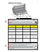
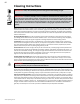
Lighting Instructions Lighting Hole Igniter Left Tube Burner Center Tube Burner Rear Burner Right Tube Burner Main Infrared Burner Off Position WARNING! Open lid WARNING! Ensure all burner controls are in the off position. Slowly turn on the gas supply valve. Main Tube Burner Lighting Rear Burner Lighting Main Infrared Burner Lighting Side Burner Lighting (optional) 1. Open grill lid. 1. Open grill lid. 1. Open grill lid. 1. Open burner cover. 2.
Cooking Instructions Initial Lighting: When lit for the first time, the gas grill emits a slight odor. This is a normal temporary condition caused by the “burn-in” of internal paints and lubricants used in the manufacturing process and does not occur again. Simply run the main burners on high for approximately one-half hour. Main Burner Use: When searing foods, we recommend preheating the grill by operating all main burners in the high position with the lid closed for approximately 10 minutes.
Infrared Heat Most people don’t realize that the heat source we are most familiar with, our sun, warms the earth using mainly infrared energy. This is a form of electro-magnetic energy with a wavelength just greater than the red end of the visible light spectrum but less than a radio wave. This energy was discovered in 1800 by Sir William Herschel who dispersed sunlight into its component colors using a prism.
Cleaning Instructions Warning! Always wear protective gloves and safety glasses when cleaning your grill. Warning! To avoid the possibility of burns, maintenance should be done only when the grill is cool. Avoid unprotected contact with hot surfaces. Ensure all burners are turned off. Clean grill in an area where cleaning solutions will not harm decks, lawns, or patios. Do not use oven cleaner to clean any part of this gas grill.
Maintenance Instructions We recommend this gas grill be thoroughly inspected and serviced annually by a qualified service person. WARNING! Always wear protective gloves and safety glasses when cleaning your grill. WARNING! Turn off the gas at the source and disconnect the unit before servicing. To avoid the possibility of burns, maintenance should be done only when the grill is cool. A leak test must be performed annually and whenever any component of the gas train is replaced or gas smell is present.
be done with the burner installed. Do not flex the drill bit when drilling the ports, as this will cause the drill bit to break. This drill is for burner ports only, not for the brass orifices (jets) which regulate the flow into the burner. Take care not to enlarge the holes. Ensure the insect screen is clean, tight, and free of any lint or other debris. Reinstallation: Reverse the procedure to reinstall the burner. Check that the valve enters the burner when installing.
Troubleshooting Problem Possible Causes Solution Low heat / Low flame when valve turned to high. For propane - improper lighting procedure. Ensure lighting procedure is followed carefully. All gas grill valves must be in the off position when the tank valve is turned on. Turn tank on slowly to allow pressure to equalize. See lighting instructions. For natural gas - undersized supply line. Pipe must be sized according to installation code. For both gases - improper preheating.
Problem Possible Causes Solution Burner output on “high” setting is too low. (Rumbling noise and fluttering blue flame at burner surface.) Lack of gas. Check gas level in propane cylinder. Supply hose is pinched. Reposition supply hose as necessary. Dirty or clogged orifice. Clean burner orifice. Spider webs or other matter in venturi tube. Clean out venturi tube. Propane regulator in “low flow” state. Ensure lighting procedure is followed carefully.
KEEP YOUR RECEIPT AS PROOF OF PURCHASE TO VALIDATE YOUR WARRANTY. Ordering Replacement Parts Warranty Information MODEL: DATE OF PURCHASE: SERIAL NUMBER: (Record information here for easy reference) Before contacting the Customer Care Department, check the NAC Website for more extensive cleaning, maintenance, troubleshooting and parts replacement instructions at www.napoleongrills.com. Contact the factory directly for replacement parts and warranty claims.
Caution! During unpacking and assembly we recommended you wear work gloves and safety glasses for your protection. Although we make every effort to make the assembly process as problem free and safe as possible, it is characteristic of fabricated steel parts that the edges and corners might be sharp and could cause cuts if handled incorrectly. Getting Started 1. Remove all cart panels, hardware, and grill head from carton. Raise lid and remove any components packed inside.
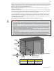
BUILT-IN UNIT OPENING DIMENSIONS OUTDOOR GFI ELECTRICAL OUTLET RECOMMENDED - LOCATE ON RIGHT SIDE OF GRILL FOR ROTISSERIE USE. BUILT-IN SIDEBURNER W H D mm) D 1¾” ) m (44m H 27 5” (1 1¾” ) m (44m NLET GAS I W NLET GAS I 34” (864mm) RECOMMENDED ING OPEN ING OPEN L A ATERI M TIBLE S U B M CO NON- MINIMUM 10 SQ IN OF VENTILATION REQUIRED ON EACH END OF CABINET WARNING! CABINET FRAME, CABINET AND COUNTER TOP MUST BE MADE FROM NON-COMBUSTIBLE MATERIAL.
BUILT-IN ACCESSORY OPENING DIMENSIONS BIZC450 / BIZC600 BUILT-IN ZERO CLEARANCE SHELLS FOR ENCLOSURES BUILT WITH COMBUSTIBLE MATERIALS Note: Accessory frames overlap opening by 1 ¾” on all 4 sides.
OPENING DIMENSIONS PART # DESCRIPTION W H N370-0361 PF STYLE STAINLESS STEEL DOOR PICTURE 17” (432mm) 23 ¼” (591mm) N370-0359 PF STYLE STAINLESS STEEL SINGLE DRAWER 17 ¼” (438mm) 6 ¾” (171mm) 23” (584mm) N370-0360 PF STYLE STAINLESS STEEL TRIPLE DRAWER 17 ¼” (438mm) 22 ¾” (578mm) 23” (584mm) N370-0502 N370-0503 DOUBLE DOOR SMALL DOUBLE DOOR LARGE * FRAMES PROTRUDE FROM FACE OF CABINET BY ¾” 28 ¼” (718mm) 37 ¾” (959mm) 20 ¼” (514mm) 20 ¼” (514mm) N370-0504 N370-0505 SIDE BURNER NAT
BI ACCESSORY DRAWER INSTRUCTIONS 1. Unpack the drawer frame assembly. 2. Remove the drawers from the enclosure by fully extending them and then lifting up to remove them from the slides. 3. Shim the opening to ensure that the enclosure fits snuggly into the opening. Ensure that the side shims are located at the same height as the enclosure mounting holes. The bottom of the opening may need to be shimmed as well to ensure that the front of the enclosure is plumb. 4.
BIPRO600 BUILT-IN INSTRUCTIONS 4 x N570-0086 (#14 X1/2”) 3/8”(10mm) N080-0213 N570-0086 N080-0213 N570-0086 N715-0081 N010-0281 W445-0031 N010-0569 This grill is designed for masonry, NON-COMBUSTIBLE enclosures only, and must be installed and serviced by a qualified installer to local codes. 1. Attach side mounting brackets to each side of the grill using #14 x 1/2" screws (N570-0086). 2. Lay the rear trim piece across the back of the opening.
N305-0027 Ensure holes in sear plates are positioned to the front of the grill. www.napoleongrills.
Leak Testing Instructions WARNING! A leak test must be performed annually and each time a cylinder is hooked up or if a part of the gas system is replaced. Warning! Never use an open flame to check for gas leaks. Be certain no sparks or open flames are in the area while you check for leaks. Sparks or open flames will result in a fire or explosion, damage to property, serious bodily injury, or death.
Rotisserie Kit Assembly Instruction (optional) Assemble rotisserie kit components as shown. Ensure stop bushing is tightened on the inside of hood casting. www.napoleongrills.
www.napoleongrills.
Parts List Item Part # Description 600RBI 1 n135-0036g left side lid casting x 2 n135-0037g right side lid casting x 3 n715-0091 trim left side lid casting x 4 n715-0092 right side lid casting x 5 n335-0053 stainless steel lid insert x n585-0070 lid heat shield x 6 n010-0684 lid handle x 7 n385-0191 NAPOLEON logo x w450-0005 logo spring clips x n510-0002 black silicone lid bumper x 8 n080-0253g lid handle cover x 9 n570-0013 #8 x 5/8” screw x 10 n570-001
Parts List Item Part # Description 600RBI n455-0008 #53 main burner orifice n 29 n357-0015 electronic ignition x 30 n570-0086 #14 x 1/2” screw x 31 n685-0004c temperature gauge x 32 n010-0178k hood assembly x 33 n010-0688 base / cuve x 34 n475-0016 rotisserie mount x 35 n570-0019 10-24 x 1/4” screw x 36 n475-0162nt control panel x 37 n010-0569 drip pan x 38 n010-0281 manifold flex connector x 39 w445-0031 union fitting 3/8” - 3/8” x 40 n715-0081 rear
57 FAX TO: 705 727 4282 ACCESSORIES & PARTS ORDER FORM PLEASE PRINT CLEARLY CONTACT NAME:______________________________________________________________________ SHIP TO :_____________________________________________________________________________ _________________________________________________________________________________________ _________________________________________________________________________________________ ___________________________________________________________________________________
58 NOTES www.napoleongrills.
28 NOTES www.napoleongrills.