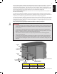
This gas grill must be used only outdoors in a well-ventilated space and must not be used inside a building, garage, screened-in porch, gazebo or any other enclosed area. EN APPLY SERIAL NUMBER LABEL FROM CARTON Serial No. XXXXXX000000 MODEL NO. FR PG.29 BILEX730 WARNING! CABINET FRAME, CABINET AND COUNTER TOP MUST BE MADE FROM NON-COMBUSTIBLE MATERIAL. DANGER IF YOU SMELL GAS: • Shut off gas to the appliance. • Extinguish any open flame. • Open lid.
EN THANK YOU FOR CHOOSING NAPOLEON NAPOLEON products are designed with superior components and materials, and are assembled by trained craftsmen who take great pride in their work. The burner and valve assembly are leak tested and test-fired at a quality test station. This grill has been thoroughly inspected by a qualified technician before packaging and shipping to ensure that you, the customer, receive the quality product you expect from NAPOLEON.
WARNING! Failure to follow these instructions could result in property damage, personal injury or death. Read and follow all warnings and instructions in this manual prior to operating grill. Safe Operating Practices • • • • • • • • • • • • • • • • • • • • • • • • • • • • • • • • This gas grill must be assembled exactly according to the instructions in the manual.
EN General Information This Gas Barbecue Is Certified Under Canadian And American National Standards, CAN/CSA 1.6 – 2005 and ANSI Z21.58-2005 respectively for Outdoor Gas Grills and should be installed to conform with local codes. In absence of local codes, install to the current CAN/CGA-B149.1 Propane Installation Code in Canada or to the National Fuel Gas Code, NFPA54/ANSI Z223.1 in the United States.
sized to supply the BTU/h specified on the rating plate, based on the length of the piping run. If installing a side burner, a separate line must be branched off to the side burner unit and enter the side burner opening at the specified location. If the enclosure is to house a propane cylinder, the tank portion of the enclosure must be ventilated according to local codes, and must not have communication with the cavity used to enclose the gas grill.
EN BUILT IN NATURAL GAS HOOK-UP: The piping up to the gas grill is the responsibility of the installer and piping should be located as shown in the built-in instructions. A flexible metal connector is included to simplify the installation of the unit. Connect this connector to the flare fitting on the end of the manifold. Connect the other end of the connector to the gas piping. Ensure that the connector does not pass through a wall, floor, ceiling or partition, and is protected from damage.
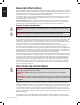
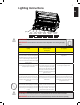
Lighting Instructions EN Lights Left Burner Rear Left Centre Centre Right Centre Infra Red Burner Burner Burner Burner Burner WARNING! Open lid. Off Position WARNING! Ensure all burner controls are in the off position. Turn on the gas supply valve. Main Burner Lighting Rear Burner Lighting (Rotisserie Burner) (if equipped) Side Burner Lighting (If equipped) 1. Open grill lid. 1. Open grill lid. 1. Open side burner cover. 2. Push and turn any main burner knob slowly to the ’hi’ position.
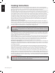
EN Cooking Instructions Initial Lighting: When lit for the first time, the gas grill emits a slight odor. This is a normal temporary condition caused by the “burn-in” of internal paints and lubricants used in the manufacturing process and does not occur again. Simply run the main burners on high for approximately one-half hour. Main Burner Use: When searing foods, we recommend preheating the grill by operating all main burners in the high position with the lid closed for approximately 10 minutes.
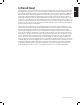
Infrared Heat 9 Most people don’t realize that the heat source we are most familiar with, our sun, warms the earth using mainly infrared energy. This is a form of electro-magnetic energy with a wavelength just greater than the red end of the visible light spectrum but less than a radio wave. This energy was discovered in 1800 by Sir William Herschel who dispersed sunlight into its component colors using a prism.
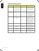
Infrared Grilling Chart EN Food Control Setting Cooking Time Helpful Suggestions Steak 1 in. (2.54cm) thick High setting 2 min. each side. 4 min. – Rare High setting 2 min. each side then medium setting. 6 min. – Medium High setting 2 min. each side then medium setting. 8 min. – Well done When selecting meat for grilling, ask for marbled fat distribution. The fat acts as a natural tenderizer while cooking and keeps it moist and juicy. High setting 2 min. each side. 4 min.
Cleaning Instructions WARNING! Always wear protective gloves and safety glasses when servicing your grill. WARNING! To avoid the possibility of burns, maintenance should be done only when the grill is cool. Avoid unprotected contact with hot surfaces. Ensure all burners are turned off. Clean grill in an area where cleaning solutions will not harm decks, lawns, or patios. Do not use oven cleaner to clean any part of this gas grill.
EN Maintenance Instructions We recommend this gas grill be thoroughly inspected and serviced annually by a qualified service person. At all times keep the gas grill area free from combustible materials, gasoline and other flammable vapors and liquids. Do not obstruct the flow of ventilation and combustion air. Keep the cylinder enclosure ventilation openings (located on the cart sides and at the front and back of the bottom shelf) free and clear from debris.
the grill, but it can also be done with the burner installed. Do not flex the drill bit when drilling the ports, as this will cause the drill bit to break. This drill is for burner ports only, not for the brass orifices (jets) which regulate the flow into the burner. Take care not to enlarge the holes. Ensure the insect screen is clean, tight, and free of any lint or other debris. Reinstallation: Reverse the procedure to reinstall the burner. Check that the valve enters the burner when installing.
EN Troubleshooting Problem Possible Causes Solution Low heat / Low flame when valve turned to high. For propane - improper lighting procedure. Ensure lighting procedure is followed carefully. All gas grill valves must be in the off position when the tank valve is turned on. Turn tank on slowly to allow pressure to equalize. See lighting instructions. For natural gas - undersized supply line. Pipe must be sized according to installation code. For both gases - improper preheating.
Problem Possible Causes Burner output on “high” Lack of gas. setting is too low. (Rumbling noise and Supply hose is pinched. fluttering blue flame at burner surface.) Dirty or clogged orifice. Infrared burner (if equipped) flashes back (during operation the burner abruptly makes a loud “whoosh” sound, followed by a continuous blow-torch type sound and grows dim.) Solution Check gas level in propane cylinder. Reposition supply hose as necessary. Clean burner orifice.
EN KEEP YOUR RECEIPT AS PROOF OF PURCHASE TO VALIDATE YOUR WARRANTY. Ordering Replacement Parts Warranty Information MODEL: DATE OF PURCHASE: SERIAL NUMBER: (Record information here for easy reference) Before contacting the Customer Solutions Department, check the NAC Website for more extensive cleaning, maintenance, troubleshooting and parts replacement instructions at www.napoleongrills. com. Contact the factory directly for replacement parts and warranty claims.
CAUTION! During unpacking and assembly we recommended you wear work gloves and safety glasses for your protection. Although we make every effort to make the assembly process as problem free and safe as possible, it is characteristic of fabricated steel parts that the edges and corners might be sharp and could cause cuts if handled incorrectly. Getting Started 1. Remove all cart panels, hardware, and grill head from carton. Raise lid and remove any components packed inside.
BUILT-IN UNIT OPENING DIMENSIONS EN MODEL OPENING DIMENSIONS NOTES W D H BILEX730 43 1/4” 1099mm 21 3/8” 543mm 7 1/2” 191mm SIDE BURNER 12 3/4” 324mm 16 1/2” 419mm 4 1/2” 114mm OPENING OF AT LEAST 5 SQ (32cm2) IN MUST BE PROVIDED FOR COMBUSTION AIR FOR SIDE BURNER. BUILT-IN SIDEBURNER OUTDOOR GFI ELECTRICAL OUTLET RECOMMENDED - LOCATE ON SAME SIDE OF GRILL AS ROTISSERIE BRACKET. Note: Accessory frames overlap opening by 1 ¾” (4cm) on all 4 sides.
BUILT-IN ACCESSORY OPENING DIMENSIONS OPENING DIMENSIONS PART # DESCRIPTION N370-0361 PICTURE W H D PF STYLE STAINLESS STEEL DOOR 17” (432mm) 23 ¼” (591mm) N370-0359 PF STYLE STAINLESS STEEL SINGLE DRAWER 17 ¼” (438mm) 6 ¾” (171mm) 23” (584mm) N370-0360 PF STYLE STAINLESS STEEL TRIPLE DRAWER 17 ¼” (438mm) 22 ¾” (578mm) 23” (584mm) N370-0502 N370-0503 DOUBLE DOOR SMALL DOUBLE DOOR LARGE * FRAMES PROTRUDE FROM FACE OF CABINET BY ¾” 28 ¼” (718mm) 37 ¾” (959mm) 20 ¼” (514mm) 20 ¼” (51
EN BI ACCESSORY DRAWER INSTRUCTIONS 1. Unpack the drawer frame assembly. 2. Remove the drawers from the enclosure by fully extending them and then lifting up to remove them from the slides. 3. Shim the opening to ensure that the enclosure fits snuggly into the opening. Ensure that the side shims are located at the same height as the enclosure mounting holes. The bottom of the opening may need to be shimmed as well to ensure that the front of the enclosure is plumb. 4.
BILEX730 BUILT-IN INSTRUCTIONS 6 x N570-0073 (1/4-20 X 3/8”) EN 3/8”(10mm) This grill is designed for masonry, NON-COMBUSTIBLE enclosures only, and must be installed and serviced by a qualified installer to local codes. 1. Attach side mounting brackets to each side of the grill using #1/4-20 x 3/8" screws (N570-0073). 2. Lay the rear trim piece across the back of the opening. To keep it in place, a dab of silicone may be applied to each wing of the rear trim. 3.
EN www.napoleongrills.
EN Rotisserie Kit Assembly Instruction (optional) Assemble rotisserie kit components as shown. Ensure stop bushing is tightened on the inside of hood casting. www.napoleongrills.
EN Leak Testing Instructions WARNING! A leak test must be performed annually and each time a cylinder is hooked up or if a part of the gas system is replaced. WARNING! Never use an open flame to check for gas leaks. Be certain no sparks or open flames are in the area while you check for leaks. Sparks or open flames will result in a fire or explosion, damage to property, serious bodily injury, or death.
31 35 36 33 22 34 6 10 8 1 37 32 42 52 7 11 30 17 9 18 28 43 54 25 38 39 41 40 56 57 55 3 24 4 5 23 2 53 49 46 26 15 51 20 50 21 47 48 29 45 27 44 12 13 14 16 58 25 EN www.napoleongrills.
EN Parts List Item Part # Description 1 N135-0042-GY1HT left side lid casting x 2 N135-0043-GY1HT right side lid casting x 3 N335-0045L-M04 stainless steel lid insert x 4 N585-0082 lid heat shield x 5 N570-0091 1/4-20 x 1/2” screw x 6 N010-0740 lid handle x 7 N385-0129-SER NAPOLEON logo x 8 W450-0005 logo clips x 9 N510-0013 black silicone lid bumper x 10 N080-0287-GY1HT lid handle cover x 11 N570-0042 #10-24 x 3/8” screw x 12 N570-0015 lid pivot screw x
Parts List Item Part # Description 45 N080-0216 bracket unit mount x 46 N010-0499 infra red main burner x 47 N565-0002 infrared burner screen x 48 N080-0207-M05 support bracket infra red burner x 49 N215-0007-M05 deflector infra red main burner x 50 N010-0527P infra red rear burner p N010-0527N infra red rear burner n N455-0051 rear burner orifice #1.
Notes EN www.napoleongrills.
Ce gril doit être utilisé uniquement à l’extérieur, dans un endroit bien aéré et ne doit jamais être utilisé à l’intérieur d’un bâtiment, d’un garage, un gazebo, une véranda avec paramoustique, ou de tout autre endroit fermé. APPOSEZ LÉTIQUETTE DU NUMERO DE SERIE DU CARTON NO de série XXXXXX000000 NO DE MODÈLE FR BILEX730 AVERTISSEMENT! LA CHARPENTE DU CABINET, LE CABINET ET LE COMPTOIR DOIVENT ÊTRE FAITS DE MATÉRIAUX INCOMBUSTIBLES.
FR MERCI D’AVOIR CHOISI NAPOLÉON Les produits NAPOLÉON sont conçus avec des composants et des matériaux de qualité supérieure, assemblés par des artisans qualifiés qui sont fiers de leur travail. Le brûleur et le montage de la soupape subissent un test de détection de fuites et d’allumage à une station de test de qualité.
AVERTISSEMENT! Si ces instructions ne sont pas suivies, des dommages matériels, des blessures corporelles ou des pertes de vie pourraient s’ensuivre. Lisez et respectez tous les avertissements et les instructions de ce manuel avant de faire fonctionner le gril. Pratiques Sécuritaires D’utilisation • • • • • • • • • • • • • • • • • • • • • • • • • • • • • • • • Ce gril à gaz doit être assemblé conformément aux instructions du manuel.
FR Information Générale Ce gril à gaz est certifié selon les normes nationales canadiennes et américaines, CAN/cSa-1.6-2005 et ANSI Z21.58 -2005 pour les grils à gaz extérieurs et son installation doit être conforme aux codes locaux. En l’absence de codes locaux, l’installation doit être conforme au Code d’installation du gaz CAN/CGA-B149.1 au Canada ou au National Fuel Gas Code, NFPA54/ANSI Z223.1 aux États-Unis.
L’installation doit se conformer au Code d’installation du gaz naturel et du propane CAN B149.1 au Canada ou au National Fuel Gaz Code ANSI Z223.1 aux États-Unis. Vous devez avoir une pipe de conducteur hors du quat d’adé de gaz pour fournir ce gril le gaz de BTU/h indiqué sur la plaque de contrôle, basée sur la longueur de la course de tuyauterie.
FR BRANCHEMENT DU GRIL ENCASTRÉ AU GAZ NATUREL: La tuyauterie jusqu’au gril à gaz est la responsabilité de l’installateur et doit être positionnée comme illustré dans le manuel d’instructions du gril encastré. Un raccord flexible métallique est inclus afin de faciliter l’installation de l’appareil. Branchez ce raccord au raccord évasé de situé à l’extrémité du collecteur. Branchez l’autre extrémité du raccord à la conduite de gaz.
Instruction D’allumage FR Lumières Brûleur de Bruleur Brûleur de Brûleur de Brûleur de Brûleur de gauche d’arriere centre gauche centre centre droite infrarouge Fermez AVERTISSEMENT! Ouvrez le couvercle. AVERTISSEMENT! Assurez-vous que tous les boutons de contrôle sont à « off ». Ouvrez ensuite la soupape d’alimentation en gaz. Allumage Du Brûleur Principal Allumage Du Brûleur Arrière Rotissérie Brûleur (si équipé) Allumage Du Brûleur Latéral (si équipé) 1. Ouvrez le couvercle. 1.
FR Instructions D’opération Éclairage initial: Lorsqu’il est allumé pour la première fois, le gril dégagera une légère odeur. Ceci est un phénomène normal et temporaire causé par l’évaporation des peintures et lubrifiants internes utilisés dans le processus de fabrication et ne se reproduira plus. Allumez simplement les brûleurs de cuve à “high” pendant une demi-heure.
Chaleur Infrarouge 37 La plupart des gens ne réalisent pas que la source de chaleur qui nous est la plus familière et que le soleil émet pour réchauffer la planète est l’énergie infrarouge. L’énergie infrarouge est une forme d’énergie électromagnétique dont la longueur d’onde est tout juste plus grande que la lumière rouge visible du spectre lumineux mais plus petite que les ondes radios.
Tableau de cuisson à l’infrarouge Aliment Réglage Des Contrôles Temps De Cuisson Conseils Pratiques Steak 1” (2.54cm) d’épaisseur Réglage à “high” 2 min chaque côté 4 min - Saignant Réglage à “high” 2 min chaque côté ensuite réglage à “medium” 6 min - À point Réglage à “high” 2 min chaque côté ensuite réglage à “medium” 8 min - Bien cuit Lorsque vous choisissez votre viande, demandez une viande qui est marbrée.
Nettoyage AVERTISSEMENT! Portez toujours des gants protecteurs et des lunettes de sécurité lorsque vous l'entretien votre gril. AVERTISSEMENT! Assurez-vous que les brûleurs sont éteints avant de nettoyer. Éviter tout contact avec les surfaces chaudes. Nettoyez votre gril dans un endroit où les produits de nettoyage n’endommageront pas votre patio, terrain ou terrasse. N’utilisez pas de produit de nettoyage à fourneau pour nettoyer votre gril.
Instructions D’entretien Nous vous conseillons de faire inspecter ce gril à gaz annuellement par un technicien de service qualifié. L'emplacement du gril à gaz doit être gardé libre de tous matériaux combustibles, essence ou autres liquides et vapeurs inflammables en tout temps. Les apports d’air comburant et d’air de ventilation ne doivent pas être obstrués.
Brûleur De Cuve : Le brûleurs soyez fabriqué en acier inoxydable 304 de calibre épais, mais puisqu’il est soumis à des chaleurs extrêmes et à un environnement corrosif, la corrosion superficielle finit par survenir. Utilisez une brosse en laiton pour enlever la corrosion superficielle. Nettoyez tous les orifices obstrués à l’aide d’un trombone déplié. N’agrandissez pas les orifices du brûleur. ATTENTION! AUX ARAIGNÉES Les araignées et les insectes sont attirés par l’odeur du propane et du gaz naturel.
FR Protection Du Brûleur Infrarouge: Le brûleur infrarouge de votre gril est conçu pour vous offrir une longue durée de vie. Cependant, certaines précautions doivent être prises afin d’éviter que les surfaces en céramiques ne fissurent, causant ainsi un mauvais fonctionnement du brûleur. Vous trouverez ci-dessous les causes de fissuration les plus courantes ainsi que les moyens à prendre pour les éviter.
Guide De Dépannage Problème Causes possibles Solutions Faible chaleur/petite flamme lorsque le bouton de contrôle est à “high”. Pour le propane - procédure d’allumage incorrect. Assurez-vous que la procédure d’allumage est suivie à la lettre. Tous les boutons de contrôle du gril doivent être fermés lorsque vous ouvrez la soupape de la bonbonne. Tournez la soupape de la bonbonne lentement pour assurer l’équilibre de la pression. Voir les instructions d’allumage.
FR Problème Causes possibles Solutions Le régulateur murmure lorsque l’appareil fonctionne. Problème normal par temps chaud. Ceci n’est pas un défaut. Le murmure est causé par une vibration à l’intérieur du régulateur et n’affecte en rien la performance et la sécurité du gril à gaz. Les régulateurs émettant un murmure ne seront pas remplacés. Les brûleurs ne s’allument pas les uns aux autres. Sales ou corrodés supports légers croix. Nettoyez ou remplacez au besoin.
GARDEZ VOTRE REÇU COMME PREUVE D’ACHAT POUR VALIDER VOTRE 45 Commande De Pièces De Rechange Information Sur La Garantie MODÈLE: FR DATE D’ACHAT: NUMÉRO DE SÉRIE: (Inscrivez l’information ici pour y avoir accès facilement.) Avant de contacter le département du service aux consommateurs, consultez le site Web de NAC pour obtenir plus d’instructions sur le nettoyage, l’entretien, le dépannage et le remplacement des pièces à www.napoleongrills.com.
ATTENTION! Lors du déballage et de l’assemblage, nous vous conseillons de porter des gants de travail et des lunettes de sécurité pour votre protection. Malgré tous nos efforts pour assurer que l’assemblage soit aussi sécuritaire et sans problème que possible, il se peut que les bords et les coins des pièces usinées en acier soient coupants et qu’ils causent des coupures si les pièces ne sont pas manipulées correctement. Pour Commencer FR 1.
DIMENSIONS D’OUVERTURE POUR LES GRILS ENCASTRÉS MODEL OPENING DIMENSIONS NOTES W D H BILEX730 43 1/4” 1099mm 21 3/8” 543mm 7 1/2” 191mm BRÛLEUR LATÉRAL 12 3/4” 324mm 16 1/2” 419mm 4 1/2” 114mm OPENING OF AT LEAST 5 SQ (32cm2) IN MUST BE PROVIDED FOR COMBUSTION AIR FOR SIDE BURNER.
DIMENSIONS D’OUVERTURE POUR LES ACCESSOIRES DIMENSIONS D’OUVERTURE N° DE PIÈCE DESCRIPTION N370-0361 PORTE EN ACIER INOXYDABLE STYLE PRESTIGE V N370-0359 TIROIR SIMPLE EN ACIER INOXYDABLE STYLE PRESTIGE V FR ILLUSTRATION L H P 17” (432mm) 23 ¼” (591mm) 17 ¼” (438mm) 6 ¾” (171mm) 23” (584mm) 17 ¼” (438mm) 22 ¾” (578mm) 23” (584mm) 28 ¼” (718mm) 37 ¾” (959mm) 20 ¼” (514mm) 20 ¼” (514mm) 12 ¾” (324mm) 12 ¾” (324mm) 4 ½” (114mm) minimum P N370-0360 TIROIR TRIPLE EN ACIER INOXYDABLE ST
INSTRUCTIONS D’INSTALLATION DES TIROIRS 1. Déballez l’assemblage du cadre et des tiroirs 2. Retirez les tiroirs du cadre en les ouvrant complètement puis en les soulevant pour les retirer des glissières. 3. Placez des cales pour vous assurer que le cadre soit bien ajusté dans l’ouverture. Assurez-vous que les cales soient situées à la même hauteur que les trous de fixation du cadre. Le bas de l’ouverture peut aussi nécessiter des cales afin d’assurer que l’avant du cadre soit d’aplomb. 4.
INSTRUCTIONS POUR LE GRIL ENCASTRÉ BILEX730 FR 6 x N570-0073 (1/4-20 X 3/8”) 3/8”(10mm) Ce gril est conçu pour des cabinets INCOMBUSTIBLES OU EN MAÇONNERIE seulement et doit être installé et entretenu par un installateur qualifié selon les codes locaux. 1. Fixez les supports de fixation latéraux à chaque côté du gril à l’aide des vis 1/4-20 x 3/8" screws (N570-0073). 2. Placez la moulure arrière le long de l’arrière de l’ouverture.
FR www.napoleongrills.
Instructions D’assemblage De L’ensemble De Rôtissoire (optionnelle) Assemblez les composantes de la rôtissoire tel qu’illustré. Assurez-vous que la bague d’arrêt soit serrée à l’intérieur de la hotte. FR www.napoleongrills.
Test De Détection De Fuites AVERTISSEMENT! Il doit être fait avant la première utilisation, annuellement et à chaque fois qu’une pièce du système de gaz est remplacée ou réparée AVERTISSEMENT! N’utilisez pas une flamme nue pour vérifier pour des fuites de gaz. Assurezvous qu’il n’y ait aucune étincelle ni flamme nue à proximité de l’endroit à vérifier. Les étincelles ou les flammes nues provoqueront un feu ou une explosion, causant des dommages matériels, des blessures graves ou des pertes de vie.
www.napoleongrills.
Liste Des Pièces Article N° de pièce Description 1 N135-0042-GY1HT moulage gauche du couvercle x 2 N135-0043-GY1HT moulage droit du couvercle x 3 N335-0045L-M04 appliqué pour couvercle en acier inoxydable x 4 N585-0082 pare-chaleur x 5 N570-0091 vis 1/4-20 x 1/2” - pointe x 6 N010-0740 poignée du couvercle x 7 N385-0129-SER logo NAPOLÉON x 8 W450-0005 clips pour logo x 9 N510-0013 pare-chocs du couvercle (silicone noire) x 10 N080-0287-GY1HT couverture poignée du
FR Liste Des Pièces Article N° de pièce Description 44 N715-0086 moulage arriére x 45 N080-0216 support de fixation de l’appareil x 46 N010-0499 infrarouge brûleur principal x 47 N565-0002 écrans infrarouge brûleur principal x 48 N080-0207-M05 support infrarouge brûleur principal x 49 N215-0007-M05 déflecteur infrarouge brûleur principal x 50 N010-0527P infrarouge brûleur arriére p N010-0527N infrarouge brûleur arriére n N455-0051 orifice de brûleur arriére #1.
Notes 57 FR www.napoleongrills.
Notes
Notes
N415-0326