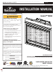
NATURAL GAS MODELS: BX42NTRE ADD PRODUCT CODE HERE (TRADE GOTHIC LT STD FONT) ENGLISH PROPANE GAS MODELS: BX42PTRE FRENCH PG. 69 INSTALLATION MANUAL ADD MANUAL TITLE Product Name / Code (MUST use title from Price Book) SAFETY INFORMATION ! Ascent™ BX42 ADD ____ ILLUSTRATED WARNING FIRE OR EXPLOSION HAZARD Failure to follow safety warnings exactly could result in serious injury, death, or property damage.
EN safety information ! WARNING • • • • • • • • • • • • • • • • • • • • • • • • • • 2 DANGER This appliance is hot when operated and can cause severe burns if contacted. Any changes or alterations to this appliance or its controls can be HOT GLASS WILL CAUSE dangerous and is prohibited. BURNS. Do not operate appliance before reading and understanding operating instructions. Failure DO NOT TOUCH GLASS UNTIL to operate appliance according to operating instructions could cause fire or injury. COOLED.
safety information EN ! WARNING • • • • • • • • • • • • • • • • • Do not use a blower insert, heat exchanger insert or other accessory not approved for use with this appliance. This appliance must not be connected to a chimney flue pipe serving a separate solid fuel burning appliance. Do not use this appliance if any part has been under water.
EN table of contents 1.0 2.0 3.0 4.0 5.0 general information 5 1.1 rates and efficiencies 5 1.2 installation overview 6 1.3 rating plate information 8 1.4 mobile home installation 8 1.5 hardware list 9 1.6 front frame installation 9 1.7 dimensions 10 1.8 optional heat management system 11 venting requirements 12 2.1 typical venting installation 14 2.1.1 corner termination 15 2.2 minimum air terminal location clearances 16 2.3 top exit - all terminations 17 2.4 rear exit - horizontal termination18 2.
standard checklist EN Installer: please fill out appliance checklist in the owner’s manual 1.0 general information When the appliance is installed at elevations above 4,500ft (1372m), and in the absence of specific recommendations from the local authority having jurisdiction, the certified high altitude input rating shall be reduced at the rate of 4% for each additional 1,000ft (305m). Expansion / contraction noises during heating up and cooling down cycles are normal and are to be expected.
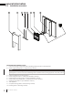
EN general information 1.2 installation overview 9 10 7 6 4 3 5 2 Sa fet yB arr ier Recommended installation steps: 1. Determine venting requirements before deciding the final location of the appliance. 2. Install rough framing (refer to “rough framing” section). note: For Universal Heat Management installation steps, refer to the leaflet provided with the Universal Heat Management kit. Start Universal Heat Management installation before placing appliance in its final position. 3. 4. 5. 6. 7.
general information EN ! WARNING • Always light the pilot whether for the first time or if the gas supply has run out, with the glass door opened or removed. • Provide adequate clearance for servicing and operating the appliance. • Provide adequate ventilation. • Never obstruct the front opening of the appliance. • Objects placed in front of the appliance must be kept a minimum of 48” (121.9cm) from the front face of the appliance.
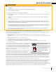
EN general information 1.3 rating plate information This illustration is for reference only. Refer to the rating plate on the appliance for accurate information. E L Certified to Canadian and American National Standards: CSA 2.22-XXXX / ANSI Z21.50-XXXX for Vented Decorative Gas Appliances ces es z décoratif à évacu évacua Certifié selon les normes Nationales Canadiennes et Américaines: CSA 2.22-XXXX / ANSI Z21.50-XXXX pour les Appareils à gaz évacuation Direct vent, vented gas fireplaces.
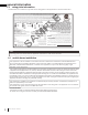
1.5 general information hardware list 1 2 3 4 5 6 Ref. # Description Quantity 1 Self-drilling screw 2 2 1/4” Hex, 1/2” long sheet metal screw 28 3 2 1/2” long sheet metal screw 4 4 Quad drive sheet metal screw 4 5 Sheet metal screw 4 6 Pan head quad screw 4 EN note: Only fasteners supplied with the appliance will be illustrated. 1.6 front frame installation #2 X6 Install the front frame using 6 screws (supplied). note: The front frame must be installed.
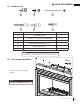
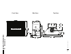
Side View Top View PP PP EN 1.7 dimensions general information PP PP PP PP PP *$6 ,1/(7 PP PP W415-2920 / B / 04.26.
general information 1.8 EN optional heat management system The Universal Heat Management system is an optional gravity vent kit that allows you to manage the heat produced by the appliance at and around the fireplace. We recommend installing the Universal Heat Management system kit during the installation of the appliance BEFORE the gas is installed. For more information, contact your local authorized dealer.
EN venting requirements 2.0 venting requirements ! WARNING • • Risk of fire. Maintain specified air space clearances to vent pipe and appliance. The vent system must be supported every 3’(0.9m) for both vertical and horizontal runs. Use support ring assembly W010-0067 or equivalent non-combustible strapping to maintain the minimum clearance to combustibles for both vertical and horizontal runs. Spacers are attached to the inner pipe at predetermined intervals to maintain an even air gap to the outer pipe.
venting requirements EN For optimum flame appearance and appliance performance, keep the vent length and number of elbows to a minimum. The air terminal must remain unobstructed at all times. Examine the air terminal at least once a year to verify that it is unobstructed and undamaged. Rigid and flexible venting systems must not be combined. Different venting manufacturer components must not be combined. These vent kits allow for either horizontal or vertical venting of the appliance.
EN venting requirements 2.1 typical venting installation ! WARNING • 24” (61cm) Maximum The first 2 feet of outer 8” (203mm) diameter vent pipe from the appliance must be wrapped in the 1” (25mm) thick insulation sleeve (supplied). 20” (50.8cm) Maximum 12” (30.5cm) Minimum base of air collar 45 5/8” (115.8cm) Minimum plus rise* 24 1/8” (61.3cm) Minimum plus rise* TOP VENT REAR VENT Special vent installation (periscope termination) Use the periscope kit to locate the air termination above grade.
venting requirements EN 16" (40.6cm) minimum 40 FT (12M) maximum 3 FT (1M) minimum base of air collar 2.1.1 corner termination The maximum vent length for a corner installation is 20” (50.8cm) of horizontal run, in addition to the 45° offset. In this case, 0” rise is acceptable when using rigid venting. When using flexible venting, it is required to maintain a 6” (152mm) rise. See illustrations below for more information. 20” (50.
EN venting requirements 2.2 minimum air terminal location clearances Covered balcony applications ††* Q S R Q MIN = 3 feet (0.9m) R MAX IHHW (4.6m) U.S.A. A 12” (30.5cm) 12” (30.5cm) Clearance above grade, veranda porch, deck or balcony. B 12” (30.5cm) 9” (229mm) Clearance to windows or doors that open. C 12” (30.5cm)* 12” (30.5cm)* D 18” (45.7cm)** 18” (45.7cm)** E 12” (30.5cm)** 12” (30.
venting requirements 2.3 EN top exit - all terminations 40’ V+H ≤ 40 ft. (For longer vent runs, a power vent is required). H ≤ 20 ft. V + H are measured from the centre of vent elbows. Elbows are considered as 90º. Two 45º elbows = One 90º elbow. 38 1/2’ (462”) 30’ 1-6 elbow zone 1-5 elbow zone 1-4 elbow zone 1-3 elbow zone 1-2 elbow zone 1 elbow zone V 20’ 15’ 10’ 5’ 3’ min. (36”) 1’ min. (12”) 0’ Base of air collar 5’ 2’ (24”) 0’ 10’ 15’ 25’ 20’ H Vertical termination only.
EN venting requirements 2.4 rear exit - horizontal termination (For vent runs that exceed the graph parameters, a power vent is required). V + H are measured from the centre of vent elbows. Elbows are considered as 90º. Two 45º elbows = One 90º elbow. 40’ 35 3/4’ (429”) 1-5 elbow zone 30’ 1-4 elbow zone 1-3 elbow zone 1-2 elbow zone V 20’ 15’ 10’ 4 3/4’ (57”) 5’ 1 1/2’ (18”) 0’ 5’ 1 1/2’ (18”) 18 0’ W415-2920 / B / 04.26.22 10’ 15’ H 20’ 17 1/4’ (207.
venting requirements 2.5 EN rear exit - vertical termination (For vent runs that exceed the graph 40’ parameters, a power vent is required). 39’ (468”) V + H are measured from the centre of vent elbows. Elbows are considered as 90º. Two 45º elbows = One 90º elbow. 1-6 elbow zone 1-5 elbow zone 1-4 elbow zone 30’ 1-3 elbow zone 1-2 elbow zone 1 elbow zone V 20’ 15’ 10’ 4 3/4’ (57”) 5’ 3 (36”) 0’ 5’ 1’ (12”) 0’ 10’ 25’ 15’ H 20’ W415-2920 / B / 04.26.
EN venting requirements 2.6 rear exit ! WARNING • Failure to create a seal to the firebox with the exhaust collar assembly will cause the appliance to function improperly and can cause injury or property damage. A. Remove the safety barrier and glass front (see "safety barrier & door removal / installation" section). B. Remove the contents from the firebox and set aside. You will need the exhaust flue collar and the top baffle (supplied). C.
venting requirements 2.8 EN top exit ! WARNING • Failure to create a seal to the firebox with the exhaust collar assembly will cause the appliance to function improperly and can cause injury or property damage. note: This appliance has been factory shipped as a top vent appliance. A. Remove the safety barrier and glass door (see "safety barrier & door removal / installation" section). B. Remove the contents from the firebox and set aside. You will need the exhaust and air inlet collar. C.
EN venting requirements F. From inside the firebox, install the 5” (127mm) exhaust collar with gasket and the exhaust outlet reducer plate up through the top of the firebox, and secure with the the 4 hex head 3/4" black screws supplied in the manual baggie (Fig. 3). note: Do not overtighten. The gasket needs only to be snug against the firebox. G. Fully secure exhaust outlet reducer using 4 self-tapping screws (supplied) (Fig. 3). I I J J J J I I H.
3.0 rough framing EN note: When using optional finishing accessories, the framing dimensions and finishing materials may differ from what is outlined in the section below; refer to the leaflet instructions supplied in the accessory kit for specific framing and finishing specifications. ! WARNING • • • • • • • • 3.
rough framing EN 3.2 minimum clearance to combustible enclosures Top Vent (Typical Application) 3” [76mm] (minimum all sides for sections of horizontal venting) outside of enclosure. COMBUSTIBLE 1” [25mm] minimum all sides for sections of vertical venting. 8” (203mm) non-combustible material NON-COMBUSTIBLE 3” (76.2mm) min.** 3” min.** (76.2mm) 72” (183cm) Ceiling (min.) BRICK 3” (76.2mm)** 0” (0MM) IF NON-COMBUSTIBLE FINISHING IS USED SUCH AS BRICK AND STONE. 1” (25mm) 52 5/8” (133.
rough framing EN Minimum Rear Vent Clearances for Typical Applications ! WARNING • Universal Heat Management kit not available for rear vent installation. For rear vent termination not exceeding 10" (254mm) of horizontal vent run. NON-COMBUSTIBLE COMBUSTIBLE INSULATED SLEEVE (SUPPLIED) 8” (203mm) noncombustible material 72” (183cm) Ceiling (min.) BRICK 3" [76mm] 52 5/8” (133.7cm) 41 1/8” (104.5cm) 1" [25mm] 0” (0MM) IF NON-COMBUSTIBLE FINISHING IS USED SUCH AS BRICK AND STONE. 24 1/8” (61.
EN rough framing Maximum Rear Vent Clearances for Typical Applications (Example 1) ! WARNING • Universal Heat Management kit not available for rear vent installation. For rear vent termination exceeding 10" (254mm). NON-COMBUSTIBLE COMBUSTIBLE INSULATED SLEEVE (SUPPLIED) 8” (203mm) noncombustible material 72” (183cm) Ceiling (min.) BRICK 3" [76mm] 52 5/8” (133.7cm) 0” (0MM) IF NON-COMBUSTIBLE FINISHING IS USED SUCH AS BRICK AND STONE. 41 1/8” (104.5cm) 1" [25mm] 24 1/8” (61.
rough framing EN Maximum Rear Vent Clearances for Typical Applications (Example 2) ! WARNING • Universal Heat Management kit not available for rear vent installation. 8” (203mm) noncombustible material INSULATED SLEEVE (SUPPLIED) 3" [76mm] 72” (183cm) Ceiling (min.) 52 5/8” (133.7cm) min. 41 1/8” (104.5cm) COMBUSTIBLE 1" [25mm] NON-COMBUSTIBLE BRICK 0” (0MM) IF NON-COMBUSTIBLE FINISHING IS USED SUCH AS BRICK AND STONE. 24 1/8” (61.
EN rough framing note: For heavier finishing materials such as marble, we recommend adding extra support to the frame. Ensure there is adequate floor support for the appliance and finishing material. Before framing your appliance, determine vent requirements before deciding the final location of the appliance. After rough framing, place the appliance in its final position. A B Ref. Minimum rough framing dimensions A 42 1/2” (108cm)* B 18 9/16” (47.1cm) *Finished inside opening 28 W415-2920 / B / 04.
4.0 venting installation EN ! WARNING • • • • • • • • • • Ensure to unpack all loose materials from inside the firebox prior to connecting the gas and electrical supply If your appliance is supplied with a remote, ensure the remote receiver is in the “OFF” position prior to connecting the gas and electrical supply to the appliance. For safe and proper operation of the appliance, follow the venting instructions exactly. The appliance exhaust flue collar must be sealed using Mill Pac.
EN venting installation 4.1 horizontal installation ! WARNING • • The firestop assembly must be installed with the vent shield to the top. Terminals must not be recessed into a wall or siding more than the depth of the return flange of the mounting plate. The vent shield must be fixed in place by fastening the extended vent shield to the bend tabs using the supplied fasteners. • This application occurs when venting through an exterior wall.
venting installation 4.2 EN vertical installation This application occurs when venting through a roof. Installation kits for various roof pitches are available from your authorized dealer / distributor. See the “accessories” section to order specific kits required. A. Determine the air terminal location, cut and frame a square opening, as illustrated, in the ceiling and the roof to provide the minimum 1" (25mm) clearance between the vent pipe and any combustible material.
EN venting installation 4.3 using either flexible vent components ! WARNING • • Do not allow the inner flex pipe to bunch up on horizontal or vertical runs and elbows. Keep it pulled tight. Spacers are attached to the inner flex pipe at predetermined intervals to maintain an even air gap to the outer flex pipe. This gap is required for safe operation. A spacer is required at the start, middle, and end of each elbow to ensure this gap is maintained. These spacers must not be removed.
venting installation 4.3.2 vertical air terminal installation EN ! WARNING • Maintain a minimum 2” (51mm) space between the air inlet base and the storm collar. note: Fastening hardware provided with appropriate roof terminal and liner kits. A. Fasten the roof support to the roof using 6 screws. The roof support is optional. In this case, the venting is to be adequately supported using either an alternate method suitable to the authority having jurisdiction or the optional roof support. B.
EN venting installation 4.3.4 restricting vertical vents ! WARNING • • • • Turn off gas and electrical supply before servicing the appliance. Appliance may be hot, do not service until appliance is cool. For safe and proper operation of the appliance, follow the venting instruction exactly. To avoid danger of suffocation, keep the packaging bag away from babies and children. Do not use in cribs, beds, carriages or play pens. This bag is not a toy. Knot before throwing away.
5.0 electrical venting information installation 5.1 EN hard wiring connection It is necessary to hard wire this appliance. This appliance must be electrically connected and grounded in accordance with local codes. In the absence of local codes, use the current CSA C22.1 Canadian Electrical Code in Canada or the ANSI/NFPA 70-1996 National Electrical Code in the United States. 5.2 receptacle wiring diagram 3 prong receptacle Electrical box cover (Black) L1 (Black) Screw (White) Cable connector 5.
EN electrical information 5.4 battery back-up installation ! WARNING • • Ensure the gas and electrical power to the appliance is turned off. Appliance may be hot, do not service until the appliance has cooled. note: In the event of a power failure, your appliance can be operated using a USB power bank as a battery back-up. A. Before beginning installation, turn off the gas and disconnect the electrical power supply from the appliance. B.
electrical information 5.5 EN initializing the transmitter for the first time ! WARNING • Ensure the gas and electrical power to the appliance is turned off. A. Locate the transmitter and receiver supplied with the appliance. B. Make sure the slide switch on the receiver is set to the “OFF” position. C. Press the battery compartment slightly into the receiver and release enabling the battery compartment to pop out. (Fig. 1). D.
EN electrical information 5.6 wiring diagram ! WARNING • Do not wire 110 volts to the valve or wall switch. W010-2763 (NG) W010-2808 (P) W190-0195 (PF0 CONTROL BOARD) PILOT SENSOR PILOT WIRE HARNESS W750-0497 SPARK ROD D UN ) EEN (GR O GR W725-0062 (NG) W725-0063 (P) (GAS VALVE) 93 -04 50 W7 ORANGE GREEN BLACK WHITE RECEIVER note: A USB power pack (not supplied) can be used during a power outage.
electrical information 5.7 EN light & blower assembly wiring diagrams LIGHTS W405-0097 LIGHTS W405-0097 POWER CORD W750-0159 WIRE HARNESS W750-0500 SWITCH W660-0009 BLOWER W062-0077 THERMODISC W690-0002 VARIABLE SPEED SWITCH W660-0019 WIRE HARNESS W750-0050 note: For EFCN/P-PF0 installation: For the lights: the switch on the control panel must remain in the ON position. For the blower: the wire harness provided with the kit must be used. W415-2920 / B / 04.26.
6.0 gas installation electrical information ! WARNING EN • • • • • • Risk of fire, explosion, or asphyxiation. Ensure there are no ignition sources such as sparks or open flames. Support gas control when attaching gas supply pipe to prevent damaging gas line. Always light the pilot whether for the first time or if the gas supply has run out with the glass door opened or removed. Purging of the gas supply line should be performed by a qualified service technician.
8.0 operation EN ! WARNING • If you do not follow these instructions exactly, a fire or explosion may result causing property damage, personal injury, or loss of life. If applicable, always light the pilot whether for the first time or if the gas supply has run out with the glass door opened or removed. • Ensure that a continuous gas flow is at the burner before installing the door. When lit for the first time, the appliance will emit an odor for a few hours.
EN operation 8.1 pilot-on-demand This appliance is equipped with an “On Demand” intermittent pilot ignition system (IPI) which also includes a continuous pilot ignition (CPI) mode with an integrated seven day timer. This system minimizes your appliance’s carbon footprint as well as reducing its annual fuel consumption and operating costs.
9.0 finish framing 9.1 EN flush ! WARNING • • • Risk of fire! Maintain all specified air space clearances to combustibles. Failure to comply with these instructions may cause a fire or cause the appliance to overheat. Ensure all clearances (i.e. back, side, top, vent, mantel, front, etc.) are clearly maintained. Ceiling 72” (182.3cm) minimum 52 5/8” (133.7cm) minimum Drywall 41 1/8” (104.5cm) * 42 1/2” (108cm) 18 9/16” (47.1cm) W415-2920 / B / 04.26.
EN finish framing 9.2 recess 3 1/2” (89mm)** 84” (213cm) min. 47 1/2” (120.7cm) * 41 1/8” (104.5cm) * 42 1/2” (108cm) 18 9/16” (47.1cm) * Allow for finished floor and hearth thickness when setting these dimensions. ** 2” x 4” frame can be “backed” with 3/4” ply to support TV mounting hardware. 44 W415-2920 / B / 04.26.
10.0 finishing EN ! WARNING • • • Risk of fire! Never obstruct the front opening of the appliance. The front of the appliance must be finished with any non-combustible materials such as brick, marble, granite, etc., provided that these materials do not go below the specified dimension, as illustrated. Do not strike, slam, or scratch. Do not operate appliance with glass removed, cracked, or scratched. Facing and/or finishing material must never overhang into the appliance opening.
EN finishing 10.2 hood installation note: This hood must be installed, if it has not already been factory installed. A. Safety barrier and glass door must be removed. B. Install the hood, ensure it is angled downward when installed. C. As illustrated, secure using 5 screws (supplied). X5 SIDE VIEW HOOD 46 W415-2920 / B / 04.26.
finishing EN 10.3 finishing with non-combustibles ! WARNING • Non-combustible finish material must not project more than 4” (101.6mm) from the face of the screen/barrier. If greater projections are desired, increase the clearance to the sides, bottom and top by 2” (50.8mm) for every additional 1” (25.4mm) of projection. If using an optional surround, the same rules applies, starting from the top of the surround.
EN finishing 10.4 installing non-combustible board ! WARNING • The surface above the appliance gets very hot. If proper finishing materials are not used, cracking can occur. 1. Align the non-combustible panel against the appliance and secure in place with the drywall screws. 42” (106.7cm) 8” (203mm) Safet y Bar rier Joint Compound where required Joint compounds such as Durabond 90 and tapes that are resilient to heat and cracking should be used when taping and mudding seams.
finishing EN 10.5 minimum combustible mantel clearances Combustible Mantel clearance can vary according to the mantel depth. Use the graph to help evaluate the clearance needed. 0+ $( 1 , 7* (+ /7 26 24 22 20 18 16 14 12 10 8 6 4 0 A 1 2 3 4 5 6 7 8 9 10 MANTEL DEPTH B C D E Appliance Opening Hood MANTEL DIMENSIONS Ref Height Depth A 31 5/8” (80.3cm) N/A B 8" (20.3cm) 2" (51mm) C 10" (25.4cm) 4" (102mm) D 12” (30.5cm) 6" (152mm) E 14” (35.
EN finishing 10.6 clearances around appliance (TV and valuable objects) Flush installation with mantel Flush installation without mantel Recessed installation with protrusion 6” min. 6” min. TV bracket TV bracket TV bracket 2.5” min.* 2” min. (3” max. recommended) A Enclosure Enclosure Appliance opening 2.5” min.* 2” min. (3” max.
finishing EN note: • Electronic appliance temperatures must be validated at the time of installation as air flow characteristics within the room can vary and maximum acceptable operating temperatures can vary from appliance to appliance. Electronic appliances cannot be used where the electronic appliance temperature exceeds the manufacturer’s maximum allowable operating temperatures (see electronic appliance manufacturer’s specifications).
EN finishing 10.8 log placement ! WARNING • • • Failure to position the logs in accordance with these diagrams or failure to use only logs specifically approved with this appliance may result in property damage or personal injury. Logs must be placed in their exact location in the appliance. Do not modify the proper log positions, since appliance may not function properly and delayed ignition may occur. The logs are fragile and should be handled with care.
finishing Bumpout Bumpout Notch Notch 1 1 3 4 2 3 PLACE TEXT BOX HERE. NOTE: ENSURE NOMENCLATURE IS CONSISTENT THROUGHOUT. Bumpout Notch 1 4 EN PLACE TEXT BOX HERE. NOTE: ENSURE NOMENCLATURE IS CONSISTENT THROUGHOUT. Bumpout Notch 1 5 3 4 3 6 PLACE TEXT BOX HERE. NOTE: ENSURE NOMENCLATURE IS CONSISTENT THROUGHOUT. PLACE TEXT BOX HERE. NOTE: ENSURE NOMENCLATURE IS CONSISTENT THROUGHOUT. IF SPACE IS LEFT OVER, USE THIS BOX TO SHOW CORRECT FINAL LOG PLACEMENT WITH PHOTOS.
EN finishing 10.9 glowing embers Tear the embers into pieces and place along the front row of ports covering all of the burner area in front of the front centre log(#2). Care should be taken to shred the embers into thin, small irregular pieces as only the exposed edges of the fibre hairs will glow. The ember material will only glow when exposed to direct flame; however, care should be taken to not block the burner ports.
11.0 adjustments EN 11.1 venturi adjustment This appliance has an air shutter that has been factory set open according to the chart below: Regardless of venturi orientation, closing the air shutter will cause a more yellow flame, but can lead to carbonization. Opening the air shutter will cause a more blue flame, but can cause flame lifting from the burner ports. The flame may not appear yellow immediately; allow 15 to 30 minutes for the final flame colour to be established.
EN adjustments 11.3 flame characteristics It’s important to periodically perform a visual check of the pilot and burner flames. Compare them to the illustration provided. If any flames appear abnormal, call a service person. 3/8” - 1/2” (9.5mm - 12.7mm) Flame must envelop upper 3/8" to 1/2" (12.7mm - 9.5mm) of Flame sensor ELECTRONIC ILLUSTRATED 56 W415-2920 / B / 04.26.
12.0 maintenance adjustments EN ! WARNING • • • • Turn off the gas and electrical power before servicing the appliance. Appliance may be hot. Do not service until appliance has cooled. Do not use abrasive cleaners on glass. Do not paint the pilot assembly. This appliance and its venting system should be inspected before use and at least annually by a qualified service person. The following suggested checks should be performed by a qualified technician.
EN maintenance This appliance is factory equipped with 5mm ceramic glass. Use only replacement parts as supplied by the appliance manufacturer. DO NOT SUBSTITUTE MATERIALS. 12.2 annual maintenance ! WARNING • • • • Annual maintenance should be performed by a qualified service technician The firebox becomes very hot during operation. Let the appliance cool completely or wear heat resistant gloves before conducting service. Never vacuum hot embers.
maintenance EN Snap the lens out of the housing (including the metal bracket) (Fig. 2). Do not touch the halogen bulb with your bare hands. The oil from your fingertips will reduce the life of the bulb. With gloved hands gently pull the old bulb from the socket and replace with the new bulb. Reinstall the lens, by snapping it back into the housing and bend the tabs on the front of the housing back in to position. (Fig. 2) Metal bracket (Fig. 3) Gloves 12.
EN replacement partsparts 13.0 replacement ! WARNING • Failure to position the parts in accordance with this manual or failure to use only parts specifically approved with this appliance may result in property damage or personal injury. Contact your dealer for questions concerning prices and policies on replacement parts. Normally, all parts can be ordered through your Authorized dealer / distributor. For warranty replacement parts, a photocopy of the original invoice will be required to honour the claim.
13.1 overview 18 10 9 11 8 GL-709 7 Safety barrier assembly 6 19 20 5 21 55 12 13 14 16 15 17 1 2 3 4 22 55 23 55 24 55 25 55 For replacement parts, refer to "valve train assembly” section.
EN 62 replacement parts W415-2920 / B / 04.26.22 13.2 valve train assembly 17 44 28 9 22 1 29 10 23 2 32 11 25 3 33 12 26 4 44 18 42 13 38 5 35 14 39 6 15 35 40 7 16 35 41 8 Items may not appear exactly as illustrated Ref. No.
14.0 troubleshooting EN ! WARNING • • • • Always light the pilot whether for the first time or if the gas supply has run out, with the glass door open or removed. Turn off gas and electrical power before servicing the appliance. Appliance may be hot. Do not service until appliance has cooled. Do not use abrasive cleaners symptom problem Main burner flame is a blue, lazy, transparent flame. test solution Blockage in vent. - Remove blockage.
EN troubleshooting symptom Pilot will not light. Makes noise with no spark at pilot burner. Pilot sparks but will not light. problem test solution Wiring: short, loose, or damaged connections (poor flame rectification). - Verify the thermocouple/sensor is clean and the wiring is undamaged. Verify the interrupter block is not damaged or too tight. Verify connections from pilot assembly are tight; also verify the connections are not grounding out to any metal.
troubleshooting symptom problem EN test solution Lights or blower won’t function (if equipped). Control module switch in wrong position. - Verify ON/OFF switch is in the “I” position which denotes on. COM switch is unplugged. - Verify “COM” switch is plugged into the front of the control module. Flames are very aggressive. Door is ajar. - Ensure door is secured properly. Venting action is too great. - Check to ensure venting is properly sealed or restrict vent exit with restrictor plate.
EN 15.0 warranty warranty Napoleon products are manufactured under the strict Standard of the world recognized ISO 9001 : 2015 Quality Management System. Napoleon products are designed with superior components and materials assembled by trained craftsmen who take great pride in their work. The burner and valve assembly are leak and test-fired at a quality test station.
Appliance Service History This appliance must be serviced annually depending on usage. Date Dealer Name Service Technician Name Service Performed Special Concerns 16.0 service history W415-2920 / B / 04.26.
NAPOLEON N APOLEON C CELEBRATING ELEBRATING O OVER VER 4 40 0Y YEARS EARS O OME C OMFORT P RODUCTS OFF H HOME COMFORT PRODUCTS 7200, Route Transcanadienne, Montréal, Québec H4T 1A3 24 Napoleon Road, Barrie, Ontario, Canada L4M 0G8 214 Bayview Drive, Barrie, Ontario, Canada L4N 4Y8 103 Miller Drive, Crittenden, Kentucky, USA 41030 De Riemsdijk 22, 4004 LC Tiel, The Netherlands Phone: 1-866-820-8686 napoleon.
MODÈLES DE GAZ NATUREL BX42NTRE MODÈLES DE PROPANE ADD PRODUCT CODE HERE (TRADE GOTHIC LT STD FONT) FRANÇAIS FRANÇAIS BX42PTRE MANUEL ADDD’INSTALLATION MANUAL TITLE Product Name / Code (MUST use title from Price MD Book) CONSIGNES DE SÉCURITÉ ! Ascent BX42 ADD ____ ILLUSTRATED AVERTISSEMENT RISQUE D’INCENDIE OU D’EXPLOSION Incapacité à suivre ces avertissements exactement peuvent entraîner de grave blessures, des pertes de vie ou des dommages matériels.
FR consignes de sécurité ! AVERTISSEMENT • • • • • • • • • • • • • • • • • • • • • • • • • • 70 AVERTISSEMENT Cet appareil est chaud lorsqu’il fonctionne et peut causer de graves brûlures en cas de contact. Toute modification apportée à cet appareil ou aux contrôles peut être LA VITRE CHAUDE CAUSERA dangereux et est interdit. DES BRÛLURES. Ne faites pas fonctionner l’appareil avant d’avoir lu et compris les instructions NE PAS TOUCHER LA VITRE d’opération.
consignes de sécurité ! AVERTISSEMENT • • • • • • • • • • • • • • • • • FR N’utilisez pas une soufflerie intégrée, un échangeur de chaleur intégré ni un autre accessoire non approuvé pour cet appareil. Cet appareil ne doit pas être raccordé au conduit d’une cheminée desservant un autre appareil de chauffage à combustible solide. N’utilisez pas cet appareil si une partie quelconque a été submergée.
table des matières FR 1.0 information générales 1.1 1.2 1.3 1.4 1.5 1.6 1.7 1.8 2.0 3.0 exigences d’évacuation encadrement approximatif 4.1 4.2 4.3 4.3.1 5.0 4.3.2 4.3.3 4.3.4 5.1 5.2 5.3 5.4 5.5 5.6 5.7 encadrement fini 10.0 finition veilleuse sur demande 9.1 encastré 10.1 10.7 10.8 10.9 10.10 10.
liste de vérification FR Installateur: veuillez remplir la liste de contrôle de l’appareil dans le manuel du propriétaire. 1.0 information générales Lorsque l’appareil est installé à une altitude de plus de 4 5000 pieds (1372m) et en l’absence de recommandations particulières de l’autorité compétente locale, l’indice certifié du débit à haute altitude devra être réduit au taux de 4% pour chaque 1 000ft (305m) supplémentaire.
information générales FR 1.2 10 vue d’ensemble de l’installation 9 7 6 4 3 5 2 Sa fet yB arr ier Étapes d’installation recommandés: 1. Déterminer les exigences de ventilation avant de décider de l’emplacement final de l’appareil. 2. Installez l’encadrement approximatif (référez à la section « encadrement approximatif »). note: Pour les étapes d’installation du système de gestion thermique universelle, référez au feuillet fourni avec l’ensemble du système de gestion thermique universelle.
information générales ! AVERTISSEMENT • • • • • • • • • • FR Allumez toujours la veilleuse, que ce soit pour la première fois ou lorsque l’approvisionnement en gaz est épuisé, avec la porte vitrée ouverte ou retirée. Prévoyez un accès suffisant pour entretenir et opérer l’appareil. Assurez-vous d’une quantité suffisante d’air de ventilation. N’obstruez jamais l’ouverture de l’appareil.
information générales FR 1.3 information sur la plaque d’homologation Cette illustration est fournie à titre de référence seulement. Pour les renseignements exacts, consultez la plaque d’homologation fixée sur l’appareil. Certified to Canadian and American National Standards: CSA 2.22-XXXX / ANSI Z21.50-XXXX for Vented Decorative Gas Appliances Certifié selon les normes Nationales Canadiennes et Américaines: CSA 2.22-XXXX / ANSI Z21.
1.5 information générales liste des pièces FR 1 2 3 4 5 6 Réf. Description Quantité 1 Vis autotaraudeuses 2 2 1/2” vis long de feuille métallique 28 3 2/12” vis long de feuille métallique 4 4 Vis de feuille métallique (quad) 4 5 Vis de feuille métallique 4 6 #10-32 x 5/8” Pan Hd Quad 4 note: Seulement les attaches fournies avec l’appareil sont illustrées. 1.6 installation de la cadre supérieure #2 X6 Installez la cadre supérieure à l’aide de 6 vis (fourni).
Vue du côté Vue de dessus PP PP information générales PP PP PP PP 1.7 dimensions PP FR PP *$6 ,1/(7 PP W415-2920 / B / 04.26.
1.8 information générales système de gestion thermique universelle (UHM) FR Le système de gestion thermique universelle est un ensemble optionnel d’évent par gravité permettant de gérer le chaleur produite par l’appareil à l’ouverture du foyer et autour. Nous recommandons d’installer l’ensemble du système de gestion thermique universelle pendant l’installation de l’appareil AVANT que le gaz de l’appareil est installé. Pour plus d’information, consultez votre détaillant local autorisé.
exigences d'évacuation 2.0 exigences d’évacuation FR ! AVERTISSEMENT • • Risque d’incendie. Conservez les dégagements nécessaires au conduit d’évent et à l’appareil. Les courses horizontales et verticales du système doivent être supportées à tous les 3 pi (0,9m). Utilisez l’ensemble de support mural Wolf Steel W010-0067 ou des supports incombustibles équivalents afin de conserver le dégagement minimal aux matériaux combustibles pour les courses verticales et horizontales.
exigences d'évacuation Lorsque vous utilisez les composants d’évacuation Wolf Steel, n’utilisez que des composants rigides / flexibles d’évacuation Wolf Steel conjointement avec les ensembles de terminaison suivants : ensemble de terminaison murale GD422-1, GD422R-2, ST58U-1 ensemble de terminaison pour toit de pente 1/12 à 7/12 GD410, ensemble de ter minaison pour toit de pente 8/12 à 12/12 GD411, ensemble de terminaison pour toit plat GD412 ou ensemble périscopique GD401 (pour pénétration des murs sous le
exigences d'évacuation FR 2.1 installation typiques ! AVERTISSEMENT • 24” (61cm) Maximum Les premiers 2 pieds de conduit extérieur de 8” (203mm) de diamètre à partir de l’appareil doit être enveloppé dans un manchon isolant de 1” (25mm) d’épaisseur (fourni). 20” (50.8cm) Maximum 12” (30,5cm) Minimum base du collier d’air 45 5/8” (115.8cm) Minimum plus la pente* 24 1/8” (61.
exigences d'évacuation FR 16" (40.6cm) minimum 40 pi (12m) Maximum 3 pi (1m) minimum Base du collier d’air 2.1.1 installation en coin La longueur maximale du conduit pour une installation en coin est de 20 po (50,8 cm) de course horizontale, en plus du décalage de 45°. Dans ce cas, une élévation de 0” est acceptable lors de l’utilisation d’une ventilation rigide. Lors de l’utilisation d’une ventilation flexible, il est nécessaire de maintenir une élévation de 6 po (152 mm).
exigences d'évacuation FR 2.2 emplacements et dégagements minimaux de la terminaison Applications pour balcon couvert ††* Q S R Q MIN = 3 feet (0.9m) R MAX = 2 x Q ACTUAL Les terminaux du mur sont à des fins d’illustration seulement. La taille et les formes peuvent varier. Mesures des terminaux prises à partir de la sortie d’échappement, pas de la plaque de montage. É.-U. A 12” (30,5cm) 12” (30,5cm) Dégagement au-dessus du sol, d’une véranda, d’une terrasse en vois ou d’un balcon.
exigences d'évacuation 2.3 évacuation dessus - toutes terminaisons 40’ FR V+H≤ 4040 ft. ft. (Pour leslonger coursesvent d’évacuation V+H ≤ (For runs, a plus power longues, un évent de puissance est nécessaire) vent is required). H ft. ft. H≤20 ≤ 20 VV++HHsont à partir du centre des coudes de aremesurés measured from the centre of vent ventilation. Les coudes considérésas comme elbows. Elbows aresont considered 90º. 90º. 2Two 45º coude = 1 90º=coude. 45º elbows One 90º elbow.
exigences d'évacuation FR 2.4 évacuation dessus - terminaison horizontale Pour courses plus longues, (Forles vent runsd’évacuation that exceed the graphun évent de puissance esta nécessaire parameters, power vent is required). VV++HHsont à partir du centre des coudes de aremesurés measured from the centre of vent ventilation. Les coudes considérésas comme elbows. Elbows aresont considered 90º. 90º. 2Two 45º coude = 1 90º = coude. 45º elbows One 90º elbow.
2.5 exigences d'évacuation évacuation arrière - terminaison verticale FR Pour courses (For les vent runs d’évacuation that exceedplus thelongues, graph un évent de puissance est nécessaire parameters, a power vent is required). V + H sont mesurés à partir du the centre des coudes de V + H are measured from centre of vent ventilation. Les coudes considérésas comme elbows. Elbows aresont considered 90º. 90º. 2 45º 45º coude = 1 90º=coude. Two elbows One 90º elbow.
exigences d'évacuation FR 2.6 évacuation arrière ! AVERTISSEMENT • Omettre de créer un scellant à la chambre de combustion avec l’assemblage du collet d’évacuation d’air causera l’appareil de fonctionner incorrectement et pourrait causer des clessures ou des dommages matériels. A. Enlever la barrière de protection et la porte vitrée, référez la section « installation / enlèvement de la barrière de protection et la porte ». B.
exigences d'évacuation 2.8 évacuation dessus FR ! AVERTISSEMENT • Il est essentiel que le couvercle d'évacuation soit installé, si non, l'appareil ne fonctionnera pas correctement et pourrait causer des blessures ou des dommages matériels. note: Cet appareil a été expédié avec une évacuation dessus. A. B. C. Enlevez l'écran de protection et vitre de la porte (voir la section « enlèvement et installation de la porte et l'écran de protection »). Fig.
exigences d'évacuation FR F. À partir de l’intérieur de la foyer, installez le collet d’évacuation de 5” (127mm) avec le joint d’étanchéité et le plaque de réducteur de sortie d’évacuation, vers le haut du foyer et fixer en place utilisant les quatre vis noir de 3/4” à tête hexagonale fourni dans le sac manuel. note: Ne serrez pas trop les vis. Il suffit d'appuyer le joint d'étanchéité contre la chambre de combustion. G.
3.0 encadrement approximatif FR note: Lorsque vous installez les accessoires de finition optionelles, les dimensions de l’ossature et les matériaux de finition peuvent différer de ce qui est décrit dans ces instructions ci-dessous, voir les instructions fournies dans le trousse de l’accessoire pour les spécifications détaillées. ! AVERTISSEMENT • • • • • • • • 3.
encadrement approximatif FR 3.2 dégagements minimaux aux enceintes combustibles Évacuation sur le dessus (Application Typique) 3” [76mm] (minimum chaque côtés pour les sections d’évacuation horizontale) hors de l’enceinte. COMBUSTIBLE 1” [25mm] minimum tous les côtés pour les sections d’évacuation verticale. NON-COMBUSTIBLE 3” (76.2mm) min.** 8” (203mm) matériau incombustible 72” (183cm) au plafond (min.) BRICK 0” (0MM) IF 3” NON-COMBUSTIBLE (76,2mm)** FINISHING IS USED SUCH AS BRICK AND STONE.
encadrement approximatif Dégagements minimaux d’évacuation à l’arrière pour les Applications Typique FR ! AVERTISSEMENT • L’ensemble du système de gestion thermique universelle n’est pas disponible pour les installations d’évacuation arrière. Pour les applications de terminaison d’évacuation arrière qui ne dépassent pas 10" (254mm) du course d’évacuation horizontale. NON-COMBUSTIBLE COMBUSTIBLE INSULATED SLEEVE (SUPPLIED) 8” (203mm) noncombustible material 72” (183cm) au plafond (min.
encadrement approximatif FR Dégagements maximum d’évacuation à l’arrière pour les Applications Typique (Exemple 1) ! AVERTISSEMENT • L’ensemble du système de gestion thermique universelle n’est pas disponible pour les installations d’évacuation arrière. Pour l’évacuation arrière qui dépassent 10" (254mm). NON-COMBUSTIBLE COMBUSTIBLE 72” (183cm) au plafond (min.) 52 5/8” (133.
encadrement approximatif Dégagements maximum d’évacuation à l’arrière pour les Applications Typique (Exemple 2) FR ! AVERTISSEMENT • L’ensemble du système de gestion thermique universelle n’est pas disponible pour les installations d’évacuation arrière. 8” (203mm) matériau incombustible INSULATED SLEEVE (SUPPLIED) 3" [76mm] 72” (183cm) au plafond (min.) 52 5/8” (133.
encadrement approximatif FR note: Pour les matériaux de finition plus lourds comme du marbre, nous vous recommandons d’ajouter un support additionnel à l’ossature. Assurez-vous que le support de plancher est adéquat pour l’appareil et le matériau de finition. Avant d’encadrer votre appareil, déterminez les exigences d’évacuation avant de décider de l’emplacement final de l’appareil. Après l’ossature approximatif, placez l’appareil dans sa position finale. A B Réf.
4.0 installation d’évacuation ! AVERTISSEMENT • • • • • • • • • • FR Avant d’effectuer les branchements pour l’alimentation en gaz et électronique, assurez-vous de retirer toute composante non fixée à l’intérieur de la chambre de combustion. Si votre appareil comprend un système de télécommande, assurez-vous que le récepteur est à la position « OFF » avant d’effectuer les branchements pour l’alimentation en gaz et électronique.
installation d’évacuation FR 4.1 installation horizontale ! AVERTISSEMENT • • • L’espaceur coupe-feu doit être installé avec l’écran protecteur orienté vers le haut. La terminaison ne doit pas être enchâssée dans le mur ou le revêtement extérieur plus que l’épaisseur de la bride de la plaque de montage. L’écran protecteur doit être fixé en place en fixant l’écran protecteur prolongé aux languettes de courbure à l’aide des attaches fournies.
4.2 installation verticale installation d’évacuation FR Cette configuration s’applique lorsque l’évacuation se fait à travers un toit. Des ensembles d’installation pour les différentes pentes de toit sont disponibles chez votre détaillant autorisé. Voir la section « accessoires » dans le manuel du propriétairepour commander l’ensemble spécifique dont vous avez besoin. A.
installation d’évacuation FR 4.3 utilisation de composants d’évacuation flexible ! AVERTISSEMENT • Ne laissez pas la gaine flexible se tasser contre les courses horizontales ou verticales et les coudes. Gardez-la tendue. Des espaceurs sont fixés à la gaine flexible à intervalles prédéterminés afin de garder un espace vide avec le conduit extérieur. Pour que le fonctionnement soit sécuritaire, un espace vide est requis.
4.3.2 installation de la terminaison verticale installation d’évacuation FR ! AVERTISSEMENT • Conservez un espace minimale de 2 po (51mm) entre la base de la prise d’air et le collet de solin. Matériel de fixation fourni avec les ensembles de terminal pour toit et raccord appropriées. A. Fixez le support de toit au toit à l’aide de 6 vis. Le support de toit est optionnel.
installation d’évacuation FR 4.3.4 renstreignant des évents verticaux ! AVERTISSEMENT • • • • Mettez hors tension de gaz et de l’alimentation électrique avant d’intervenir sur l’appareil. Appareil peut être chaud, pas de service jusqu’à ce que l’appareil est refroidi. Pour utilisation sûre et correcte de l’appareil, suivez les instructions d’évacuation exactement. Pour éviter le risque d’asphyxie, gardez le sac d’emballage de bébés et les enfants.
5.1 5.0 information électriques branchement par câble FR It is necessary to hard wire this appliance. Vous devez effectuer un branchement par câble avec cet appareil. Une charpente permanente servant à encastrer l’appareil nécessite un branchement par câble de la boîte de dérivation de l’appareil. Cet appareil doit être raccordé électriquement et mis à la terre conformément aux codes locaux. En l’absence de codes locaux, utilisez la version vourante du Code Canadien d’Électricité CSA C22.
information électriques FR 5.4 installation du sauvegarde de pile ! AVERTISSEMENT • • Assurez-vous que le gaz et l’électricité de l’appareil sont coupés. L’appareil peut être chaud, ne pas entretenir tant que l’appareil n’a pas refroidi. note: En cas de panne de courant, votre appareil peut être utilisé avec la banque d’alimentation USB comme sauvegarde de piles. A. Avant de commencer l’installation, coupez le gaz et débranchez l’alimentation électrique de l’appareil. B.
information électriques 5.5 initialisation de la télécommande pour la première fois FR ! AVERTISSEMENT • Assurez-vous que l’alimentation électrique et du gaz sont éteints. A. Localisez la télécommande et le récepteur fournis avec l’appareil. B. Assurez que le commutateur du récepteur est dans la position « ARRÊT ». C. Appuyez légèrement sur le compartiment à piles du récepteur, puis relâchez-le afin de permettre au compartiment à piles de sortir. (Fig. 1). D.
information électriques FR 5.6 schéma câblage ! AVERTISSEMENT • Ne raccordez pas l’interrupteur mural ou la soupape de gaz à l’alimentation électrique (110V). W010-2763 (NG) W010-2808 (P) W190-0195 (PF0 CONTROL BOARD) PILOT SENSOR PILOT WIRE HARNESS W750-0497 SPARK ROD ) EEN N OU GR W725-0062 (NG) W725-0063 (P) (GAS VALVE) R D (G 93 -04 50 W7 ORANGE GREEN BLACK WHITE RECEIVER note: Un bloc d’alimentation USB (non fourni) peut être utiliser en cas d’un panne de courant.
5.7 information électriques schémas câblage des lumières et de la soufflerie FR LIGHTS W405-0097 LIGHTS W405-0097 POWER CORD W750-0159 WIRE HARNESS W750-0500 SWITCH W660-0009 BLOWER W062-0077 THERMODISC W690-0002 VARIABLE SPEED SWITCH W660-0019 WIRE HARNESS W750-0050 note: Pour l'installation EFCN/P-PF0 : Pour les feux: l'interrupteur du tableau de commande doit rester en position ON. Pour le souffleur: le faisceau électrique fourni avec le kit doit être utilisé. W415-2920 / B / 04.26.
FR 6.0 branchement du gaz branchement du gaz ! AVERTISSEMENT • • • • • • Risque d’incendie, d’explosion, ou d’asphyxie. Assurez-vous qu’il n’y ait aucune source d’allumage comme des étincelles ou une flamme nue. Soutenez le contrôle du gaz lorsque vous attachez le tuyau pour éviter de plier la conduite de gaz. Allumez toujours la veilleuse, que ce soit pour la première fois ou lorsque l’approvisionnement en gaz est épuisé, avec la porte vitrée ouverte ou retirée.
8.0 opération (électronique) ! AVERTISSEMENT • • FR Si ces instructions ne sont pas suivies à la lettre, un incendie ou une explosion pourraient s’ensuivre, causant des dommages matériels, des blessures corporelles ou des pertes de vie. Si applicable, allumez toujours la veilleuse, que ce soit pour la première fois ou lorsque l’approvisionnement en gaz est épuisé, avec la porte vitrée ouverte ou retirée. Assurez-vous que l’arrivée de gaz au brûleur est continue avant d’installer la porte.
opération (électronique) FR 8.1 veilleuse sur demande Cet appareil est équipé d’un système de veilleuse à allumage intermittent (IPI) « Sur demande » qui comprend également un mode de veilleuse permanente (CPI) avec une minuterie intégrée de sept jours. Ce système minimise l’empreinte carbone de votre appareil et réduit sa consommation annuelle de combustible ainsi que son coût de fonctionnement.
9.0 encadrement fini ! AVERTISSEMENT • • • FR Risque d’incendie! Conservez tous les dégagements aux matériaux combustibles spécifiés. Ne pas respecter ces instructions peut causer un incendie ou une surchauffe. Assurez-vous que tous les dégagements (arrière, côtés, dessus, évents, tablette, façade, etc.) sont respectés à la lettre. Ceiling 72” (182.3cm) minimum 52 5/8” (133.7cm) minimum Drywall 41 1/8” (104.5cm) * 42 1/2” (108cm) 18 9/16” (47.1cm) W415-2920 / B / 04.26.
encadrement fini FR 9.1 encastré 3 1/2” (89mm)** 84” (213cm) min. 47 1/2” (120.7cm) * 41 1/8” (104.5cm) * 42 1/2” (108cm) 18 9/16” (47.1cm) * Tenez compte de l’épaisseur du plancher et du foyer lorsque vous définissez ces dimensions. ** Le cadre de 2” x 4” peut être « renforcé » avec une pièce contraplaqué d’un épaisseur de 3/4” pour supporter le matériel de montage du téléviseur. 112 W415-2920 / B / 04.26.
10.0 finition ! AVERTISSEMENT • • • FR Risque d’incendie! N’obstruez jamais l’ouverture sur le devant de l’appareil. Si la finition de la façade de l’appareil est fait, elle doit être faite de matériau incombustible comme de la brique, du marbre du granite, etc., sous réserve que ces matériaux ne dépassent pas le dimension spécifiée, comme illustré. Ne frappez, claquez et n’égratignez pas la porte vitrée. Ne faites pas fonctionner l’appareil lorsque la porte vitrée est enlevée, fissurée, brisée ou égratignée.
finition FR 10.2 installation de l’hotte note: Cette hotte doit être installée, si elle n’est pas déjà installée. A. La porte et la barrière de protection doivent être enlevés. B. Installez l’hotte, assurez-vous qu’elle est inclinée vers le bas lorsqu’elle est installée. C. Comme illustré, fixez l’hotte utilisant 5 vis (fournies). X5 SIDE VIEW HOOD 114 W415-2920 / B / 04.26.
10.3 finition avec les matériaux incombustibles finition FR ! AVERTISSEMENT • Les matériaux de finition incombustibles ne doivent pas dépasser de plus 4” (101,6mm) la façade de la porte. Si des projection plus grandes sont requises, augmentez les dégagements des côtés et du dessus de 2” (50,8mm) pour chaque pouce (24,5mm) supplémentaire de projection. Si vous utilisez un moulure optionelle, les même règles s’applique, commençant du sommet du moulure.
finition FR 10.4 installation du panneau incombustible ! AVERTISSEMENT • La surface au-dessus l’appareil devient très chaude. Si des matériaux de finition inadéquats sont utilisés, des craquelures peuvent apparaître. 1. Alignez le panneau incombustible contre l’appareil et fixez-le avec les vis de cloison sèche. 42” (106.
finition 10.5 dégagements minimaux de la tablette combustible FR Le dégagement d’une tablette combustible à l’appareil peut varier selon la profondeur de la tablette. Utilisez le graphique pour vous aider à déterminer les dégagements nécessaire. / $ 7 $ % / ( 7 D 7 E ( H A U T E U R 26 24 22 20 18 16 14 12 10 8 6 4 0 A 1 2 3 4 5 6 7 8 9 10 PROJECTION DE LA TABLETTE (") B DIMENSIONS DE LA TABLETTE Réf Hauteur Profondeur A 31 5/8” (80.3cm) N/A B 8" (20.3cm) 2" (51mm) C 10" (25.
finition FR 10.6 dégagement autour de l’appareil (téléviseur et objets de valeur) Installation affleurant avec un manteau Installation affleurant sans un manteau Installation enchâssées avec une saillie 6” min. Support du téléviseur 6” min. Support du téléviseur Support du téléviseur 2.5” min.* Enceinte Enceinte Appareil L’ouverture de l’appareil Appareil 2” min. (3” max. recommandé) A L’ouverture de l’appareil Installation affleurant avec un manteau 6” min.
note: • • • finition FR Les températures du téléviseur doivent être validées au moment de l’installation, car les caractéristiques de débit d’air dans la pièce peuvent varier et les températures de fonctionnement maximales acceptables peuvent varier d’un appareil à l’autre. Le téléviseur ne peut pas être utilisé lorsque sa température dépasse les températures de fonctionnement maximales autorisées par le fabricant (voir les caractéristiques techniques du fabricant du téléviseur).
finition FR 10.8 disposition des bûches ! AVERTISSEMENT • • • Omettre de positionner les bûches conformément aux schémas ou omettre d’utiliser uniquement des bûches spécifiquement approuvées pour cet apareil peut causer des dommages matériels ou des blessures corporelles. Les bûches doivent être placées correctement à l’intérieur de l’appareil. Ne changez pas la position des bûches car l’appareil risque de ne pas fonctionner adéquatement et un retard d’allumage risque de se produire.
finition FR Bumpout Bumpout Encoche Encoche 1 1 3 4 2 3 Bumpout Encoche Bumpout Encoche 5 4 3 4 5 6 3 PLACE TEXT BOX HERE. NOTE: ENSURE NOMENCLATURE IS CONSISTENT THROUGHOUT. PLACE TEXT BOX HERE. NOTE: ENSURE NOMENCLATURE IS CONSISTENT THROUGHOUT. IF SPACE IS LEFT OVER, USE THIS BOX TO SHOW CORRECT FINAL LOG PLACEMENT WITH PHOTOS. IF SPACE IS LEFT OVER, USE THIS BOX TO SHOW CORRECT FINAL LOG PLACEMENT WITH LINE DRAWINGS. W415-2920 / B / 04.26.
finition FR 10.9 braises incandescentes Déchirez les braises incandescentes en morceaux et placez-les le long de la première rangée des orifices du brûleur en couvrant toute la surface à l’avant de la bûche avant centrale (#2). Les braises devraient être déchirées très soigneusement en petits morceaux minces irréguliers, car seuls les côtés exposés des fibres deviendront incandescentes.
finition 11.0 ajustements FR 11.1 réglage du venturi L’ouverture du volet d’air a été préréglée en usine selon le tableau ci-dessous: Indépendamment de l’orientation du venturi, plus le volet est fermé, plus la VENTURI flamme est jaune et aura tendance à causer des dépôts de carbone. Plus le volet est ouvert, plus la flamme est bleue et plus elle a tendance à se détacher des orifices du brûleur.
ajustements FR 11.3 caractérisques de la flamme Il est important d’effectuer périodiquement une inspection visuelle de la flamme de la veilleuse et du brûleur. Comparez-les à ces illustrations. Si des flammes paraissent anormales, contactez un technicien de service. 124 W415-2920 / B / 04.26.22 3/8” - 1/2” (9.5mm - 12.7mm) La flamme doit envelopper la sonde de flamme de 3/8" à 1/2" (9.5mm - 12.
12.0 entretien ! AVERTISSEMENT • • • • FR Coupez l’alimentation en gaz et l’alimentation électrique avant de procéder à l’entretien de l’appareil. L’appareil peut être chaud. Attendez qu’il soit refroidi avant d’en faire l’entretien. N’utilisez pas de produits abrasifs. Ne peinture pas l’assemblage de la veilleuse. Cet appareil et son système d’évacuation devraient être inspectés avant la première utilisation et au moins une fois l’an par un technicien de service qualifié.
entretien FR L’appareil est muni d’une 5mm en verre céramique. Remplacez uniquement avec une pièce pour le foyer disponible chez votre détaillant autorisé. N’UTILISEZ PAS DE MATÉRIAUX SUBSTITUTS. 12.2 entretien annuel ! AVERTISSEMENT • • • • • • • Le caisson devient trés chaud lors du fonctionnement. Laissez l’appareil se refroidir complétement ou portez des gants antichaleur avant d’effectuer l’entretien. Ne jamais aspirer des braises qui sont chaudes. Ne peinturez pas l’assemblage de la veilleuse.
entretien Cassez l’objectif hors du boîtier (avec le support métallique) (Fig 2). Ne touchez pas l’ampoule halogène à mains nues. L’huile du bout des doigts réduira la durée de vie de l’ampoule. Avec des mains gantées, retirez doucement l’ancienne ampoule de la douille et remplacez-la par la nouvelle ampoule. Réinstallez l’objectif en le cassant en retour du boîtier et pliez les pattes sur l’avant du boîtier dans leurs position. (Fig. 2) Support métallique FR (Fig. 3) Gants 12.
FR 13.0 pièces de rechange pièces de rechange ! AVERTISSEMENT • Omettre de positionner les pièces conformément à ce manuel ou d’utiliser uniquement des pièces spécifiquement approuvées pour cet appareil peut causer des dommages matériels ou des blessures corporelles. Contactez votre détaillant pour les questions concernant les prix et la disponibilité des pièces de remplacement. Normalement, toutes les pièces peuvent être commandées chez votre détaillant autorisé.
13.1 vue d’ensemble 18 10 9 11 8 GL-709 7 L’assemblage de la barrière de protection 6 19 20 5 21 55 12 13 14 16 15 17 1 2 3 4 22 55 23 55 24 55 25 55 Pour les pièces de rechanges, voir « l’assemblage de la soupape ». Ces articles peut différer de celle illustré. No.
FR 130 W415-2920 / B / 04.26.22 pièces de rechange 13.2 assemblage de la soupape 17 44 28 9 22 1 29 10 23 2 32 11 25 3 33 12 26 4 44 18 42 13 38 5 35 14 39 6 15 35 40 7 16 35 41 8 Ces articles peut différer de celle illustré No. de Réf. 1 1 2 2 3 4 5 6 7 8 9 10 No.
14.0 guide de dépannage ! AVERTISSEMENT • • • • FR Allumez toujours la veilleuse, que ce soit pour la première fois ou lorsque l’approvisionnement en gaz est épuisé, avec la porte vitrée ouverte ou retirée. Coupez l’alimentation en gaz et l’alimentation électrique avant de procéder à l’entretien de l’appareil. L’appareil peut être chaud. N’effectuez aucun entretien jusqu’à ce que l’appareil soit refroidi.
guide de dépannage FR symptôme La veilleuse ne s’allume pas. Il y a du bruit mais aucune étincelle au brûleur de la veilleuse. Étincelle à la veilleuse mais celle-ci ne s’allume pas. problème solution Câblage: pénurie, connexion desserrée (rectification de la flamme pauvres). - Aucun signal du télécommande avec ignition du veilleuse. - Reprogrammer le code du récepteur. Remplacer le récepteur. Connexion desserrée.
guide de dépannage symptôme problème FR solution Le guide suivant est pour le système de SIT seulement: La veilleuse ne s’allume pas. Aucun bruit et aucune étincelle au brûleur de la veilleuse. (Les lumières et la soufflerie fonctionnent, si équipé). La boîte d’allumage a été verrouillée. Choisissez l’une des trois méthodes suivantes pour réinitialiser le système: 1.
garantie 15.0 garantie FR Les produtits Napoléon sont fabriqués conformément aux normes strictes du Système de Gestion de la Qualité mondialement reconnu ISO 9001 : 2015. Les produits Napoléon sont conçus avec des composants et des matériaux de qualité supérieure, assemblés par des artisans qualifiés qui sont fiers de leur travail. Le brûleur et le montage de la soupape subissent un test de détection de fuite et d’allumage à une station de test de qualité.
Historique de service de l’appareil Cet appareil doit être entretenu annuellement selon son usage. Date Détaillant Nom du Technicien Travail Effectué Problèmes Particuliers 16.0 historique d’entretien garantie W415-2920 / B / 04.26.
NAPOLÉON N APOLÉON C CÉLÈBRE ÉLÈBRE P PLUS LUS D DE E4 40 0A ANS NS D D’EXISTENCE ’EEXISTENCE C ONSACRÉS À LLA AC ONCEPTIO ON D E PR RODUITS DE CONFORT CONSACRÉS CONCEPTION DE PRODUITS 7200, Route Transcanadienne, Montréal, Québec H4T 1A3 24 Napoleon Road, Barrie, Ontario, Canada L4M 0G8 214 Bayview Drive, Barrie, Ontario, Canada L4N 4Y8 103 Miller Drive, Crittenden, Kentucky, USA 41030 De Riemsdijk 22, 4004 LC Tiel, Pays-Bas Téléphone: 1-866-820-8686 napoleon.