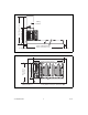
FIELDPOINT OPERATING INSTRUCTIONS AND SPECIFICATIONS cFP-2200/2210/2220 Intelligent Real-Time Controllers for Compact FieldPoint 4 5 6 3 7 8 13 9 2 14 12 10 15 1 11 Bottom Front 1 2 3 4 5 6 7 8 RS-232 Serial Port RJ-45 Ethernet Port 1 Removable Compact Flash (cFP-2220 Only) Status LED Power LED User-Configurable LEDs DIP Switches USB Port (cFP-2220 Only) 9 10 11 12 13 14 15 RJ-45 Ethernet Port 2 (cFP-2220 Only) Reset Button Power Connector Digital Input/Output Terminals (cFP-2220 Only) RS-485
This document describes how to mount the cFP-2200/2210/2220 controllers, how to connect the controllers to networks, and how to use the features of the controllers. This document also contains specifications for the controllers. In this document, the cFP-2200/2210/2220 controllers are referred to inclusively as the cFP-22xx.
has the following symbol stamped beside it: . Connect the backplane PE ground terminal to safety ground using 14 AWG (1.6 mm) wire with a ring lug. Use the 5/16 in. panhead screw shipped with the backplane to secure the ring lug to the backplane PE ground terminal. To ensure maximum cooling efficiency, mount the Compact FieldPoint so that the I/O module vents are at the top and bottom, as shown in the following figure: Figure 2.
106 mm (4.18 in.) Min. 182 mm (7.18 in.) Cabling Clearance 4 slots = 246 mm (9.68 in.) 8 slots = 441 mm (17.4 in.) Cooling Outline 51 mm (2 in.) Cooling Outline 51 mm (2 in.) Figure 3. cFP-22xx Installed on cFP-BP-x, Bottom View with Dimensions 4 slots = 246 mm (9.68 in.) 127 mm (5.00 in.) Min. 165 mm (6.50 in.) 8 slots = 441 mm (17.4 in.) Cabling Clearance Cooling Outline 51 mm (2 in.) All Around Figure 4. cFP-22xx Installed on cFP-BP-4, Front View with Dimensions cFP-2200/2210/2220 4 ni.
104.78 mm (4.1 in.) 127.00 mm 63.50 mm (2.5 in.) (5.0 in.) 407.80 mm (16.1 in.) 387.60 mm (15.3 in.) 311.40 mm (12.3 in.) 129.54 mm (5.1 in.) 33.15 mm (1.3 in.) 22.23 mm (0.9 in.) 440.94 mm (17.4 in.) Figure 5. cFP-BP-8, Back View with Dimensions 104.74 mm (4.1 in.) 127.00 mm 63.46 mm (2.5 in.) (5.0 in.) 211.84 mm (8.3 in.) 161.04 mm (6.3 in.) 84.84 mm (3.3 in.) 34.04 mm (1.3 in.) 22.19 mm (0.9 in.) 245.87 mm (9.6 in.) Figure 6.
Mounting the Backplane on a DIN Rail The DIN rail mounting kit is NI part number 778614-01. You need one kit to mount the cFP-BP-4 on a standard 35 mm DIN rail. Complete the following steps to mount the backplane on a DIN rail. 1. Fasten the DIN rail clip to the cFP-BP-4 using a number 2 Phillips screwdriver and the 8-32 × 5/16 in. countersink screws shipped with the mounting kit. L NA TS TIO MEN NA RU INST Figure 7.
3. Press down firmly on the backplane to compress the spring until the clip locks in place on the DIN rail. 4. Connect the PE ground terminal on the backplane to safety ground. Disconnect power and make sure that no I/O modules are in the backplane before removing it from the DIN rail. Caution Mounting the Backplane on a Panel The horizontal panel-mount kit has mounting holes on the sides of the backplane and is NI part number 778616-01.
102 mm (4 in.) 260 mm (10.25 in.) Figure 10. cFP-BP-4 with Horizontal Panel Mount Kit Installed, Front View with Dimensions 102 mm (4 in.) 457 mm (18 in.) Figure 11. cFP-BP-8 with Horizontal Panel-Mount Kit Installed, Front View with Dimensions L NA NTS TIO ME NATRU INS Figure 12. Installing the Vertical Panel-Mount Kit on the cFP-BP-4 cFP-2200/2210/2220 8 ni.
34.0 mm (1.34 in.) 178 mm (7.0 in.) 17.8 mm (0.70 in.) 152 mm (6 in.) 178 mm (7 in.) 7.6 mm (0.30 in.) 246 mm (9.7 in.) Figure 13. cFP-BP-4 with Vertical Panel-Mount Kit Installed, Front View with Dimensions 33.1 mm (1.31 in.) 374 mm (14.7 in.) 152 mm (6 in.) 178 mm (7 in.) 7.6 mm (0.30 in.) 17.8 mm (0.70 in.) 457 mm (18 in.) Figure 14. cFP-BP-8 with Vertical Panel-Mount Kit Installed, Front View with Dimensions 2. Bolt or screw the plates to a panel. 3.
Mounting the Backplane in a Standard 19 in. Rack The rack-mount kit for Compact FieldPoint is NI part number 778615-01. The following figure shows the dimensions of the rack-mount kit. 374.65 mm (14.750 in.) 2× 34.93 mm (1.375 in.) 2× 6.91 mm (0.272 in.) 66.29 mm (2.610 in.) 278.89 mm (10.980 in.) 177.8 mm (7.000 in.) 8× Diameter 38.1 mm (1.500 in.) ( 25.4 mm (1.000 in.) 7.92 mm +0.07 mm 0 mm 0.312 in. +0.003 in. –0.000 in. ) 63.07 mm (2.483 in.) 25.02 mm (0.985 in.) 37.69 mm (1.484 in.) 82.
AL TS TIONMEN NA RU INST Figure 16. Installing the Rack-Mount Bracket on the cFP-BP-4 AL TS TIONMEN NA RU INST Figure 17.
2. Bolt the rack-mount bracket to a standard 19 in. rack. 3. Connect the PE ground terminal on the cFP-BP-x to safety ground. Disconnect power and make sure that no I/O modules are in the backplane before removing it from the rack. Caution You can install an 8 in. DIN rail in the rack-mount kit to mount a power supply such as the PS-5. The captive #10-32 nuts on the rack-mount kit make it easy to attach a DIN rail. Use two #10-32 screws of 3/8 in. length as shown in Figure 18.
Installing the cFP-22xx on the Backplane 1. Make sure that no power is connected to the controller. 2. Make sure that the controller is right side up with the NI logo at the top, and align the captive screws on the controller with the holes on the backplane. 3. Seat the card edge at the back of the controller in the card-edge connector on the backplane. 4. Press the controller firmly to seat it on the backplane. Figure 19. Installing the Controller on the Backplane 5.
Installing I/O Modules on the Backplane 1. Align the captive screws on the I/O module with the holes on the backplane. 2. Press firmly to seat the I/O module on the backplane. 3. Using a number 2 Phillips screwdriver with a shank of at least 64 mm (2.5 in.) length, tighten the captive screws to 1.1 N · m (10 lb · in.) of torque. 4. Repeat this procedure to install additional I/O modules on the backplane. Figure 20. Installing an I/O Module on the Backplane cFP-2200/2210/2220 14 ni.
Installing Connector Blocks on the Backplane In order to connect I/O modules to input signals or loads, you need to install a cFP-CB-x connector block or other connectibility accessory for each I/O module on the backplane. Use the connector socket to the right of each I/O module socket. Do not insert or remove connector blocks or other connectivity accessories while power is applied to them. Caution 1. Wire signals or loads as described in the I/O module and connector block operating instructions.
Figure 21. Installing a Connector Block on the Backplane cFP-2200/2210/2220 4. Using a number 2 Phillips screwdriver with a shank of at least 64 mm (2.5 in.) length, tighten the captive screws to 1.1 N · m (10 lb · in.) of torque. 5. Repeat this procedure to install additional connector blocks on the backplane. 16 ni.
Connecting the cFP-22xx to a Network Connect the cFP-22xx to an Ethernet network using RJ-45 Ethernet port 1 on the controller front panel. Use a standard Category 5 (CAT-5) or better Ethernet cable to connect the controller to an Ethernet hub, or use an Ethernet crossover cable to connect the controller directly to a computer. To prevent data loss and to maintain the integrity of your Ethernet installation, do not use a cable longer than 100 m.
Wiring Power to the cFP-22xx The cFP-22xx requires an external power supply that meets the specifications in the Power Requirements section. The cFP-22xx filters and regulates the supplied power and provides power for all of the I/O modules. You must connect a power supply to at least one pair of V and C terminals. Optionally, you can connect a power supply to the other pair of V and C terminals. The controller draws power from the power supply with the higher voltage.
2. Install a tie wrap or other device on the power wires to secure the ferrite in place near the controller power connector, as shown in Figure 24. Figure 24. Ferrite Installed with Tie Wrap 3. Connect the positive lead of the power supply to the V1 terminal of the COMBICON connector shipped with the cFP-22xx. 4. Connect the negative lead of the power supply to one of the C terminals of the COMBICON connector. 5.
The controller indicates which terminal it is using on the channel called Power Source in software. A value of 0 indicates V2, and a value of 1 indicates V1. This behavior is different from that of older Compact FieldPoint controllers. If your application uses input from the Power Source channel, you must change your application to reflect the change in channel behavior. You can either make the change in software or connect the primary power supply to V2 and a backup power supply to V1.
COM 1 COM 1 is an RS-232 DTE serial port with a standard DB-9 connector. The Serial VIs access COM 1 as port 0. The following figure shows the locations of the DB-9 connector pins and Table 1 lists the signals on the pins. Pin 5 Pin 1 Pin 9 Pin 6 Figure 25. Controller Serial Port Table 1. DB-9 Pin Descriptions Pin Signal 1 DCD 2 RXD 3 TXD 4 DTR 5 GND 6 DSR 7 RTS 8 CTS 9 RI COM 2 (cFP-2210 and cFP-2220 Only) COM 2 is an RS-232 DTE serial port with a 10-position modular jack.
COM 4 (cFP-2220 Only) COM 4 is an RS-485 serial port with a 10-position modular jack. The Serial VIs access COM 4 as port 3. COM 4 has 100 Vrms of operational isolation. Use an external RS-485 isolator if your application requires more isolation. Refer to Figure 26 and Table 2 for pin locations and signal descriptions. Pin 1 Pin 10 Figure 26. 10-Position Modular Jack Pin Locations Table 2.
Figure 27 shows how to wire several FP-1001 banks in an RS-485 network controlled by the cFP-2220. Only two FP-1001 banks are shown, but the cFP-2220 can control up to 24 FP-1001 banks. Install 120 Ω termination resistors at each end of the network as shown in Figure 27. cFP-2220 COM 4 FP-1001 RXD– RXD+ TXD– TXD+ RX– 120 Ω 120 Ω RX+ FP-1001 TX– TX+ RX– 120 Ω RX+ TX– TX+ 120 Ω Figure 27.
You can use the two digital inputs to control the cFP system from LabVIEW. For example, one input could be a START/STOP switch, and the other could determine which of two VIs should run at startup. NI recommends connecting a single-pole single-throw (SPST) switch between the input terminal and one of the C terminals. The inputs have a value of 1 when the switch is closed and 0 when the switch is open. C O2 R2 LED B R1 LED A C O1 C I2 Switch 2 C I1 Switch 1 Figure 28.
Configuring DIP Switches IP RESET SAFE MODE NO APP CONS. OUT USER2 USER1 Figure 29. DIP Switches All of the DIP switches are in the OFF position when the controller is shipped from National Instruments. IP RESET Switch Push the IP RESET switch to the ON position and reboot the controller to reset the IP address to 0.0.0.0. If the controller is on your local subnet and the IP RESET switch is in the ON position, the controller appears in MAX with IP address 0.0.0.0.
NO APP Switch Push the NO APP switch to the ON position to prevent a LabVIEW RT startup application from running at startup. If you want to permanently disable a LabVIEW RT application from running at startup, you must disable it in LabVIEW. To run an application at startup, push the NO APP switch to the OFF position, create an application using the LabVIEW Application Builder, and configure the application in LabVIEW to launch at startup.
Using the Reset Button Pressing the Reset button resets the processor in the same manner as cycling power. Understanding LED Indications Figure 30. LEDs STATUS LED The STATUS LED is off during normal operation. The cFP-22xx indicates specific error conditions by flashing the STATUS LED a certain number of times as shown in Table 3. Table 3. Status LED Indications Number of Flashes Indication 1 The controller is unconfigured.
POWER LED The POWER LED is lit while the cFP-22xx is powered on. This LED indicates that the power supply connected to the controller is adequate. The POWER LED lights green when the controller is using the primary power supply and amber when the controller is using the secondary power supply. User-Configurable LEDs You can use the FieldPoint Write VI to write values to LEDs A, B, C, and D. The LEDs can have any of three values: 0 is OFF, 1 is green, and 2 is amber.
Remote Front Panels You may need to monitor and control an embedded VI remotely. The cFP-22xx supports multiple remote front panels for embedded VIs. Users can view the remote front panel using either LabVIEW or a Web browser. Users accessing the remote front panels with a Web browser need to have either Internet Explorer 5.5 Service Pack 2 or later, or Netscape 4.7 or later. If you plan to use remote front panels to control the VI, keep the front panel simple and do not use property nodes.
Troubleshooting This section contains troubleshooting instructions for the cFP-22xx and FieldPoint software. For more troubleshooting information, refer to the Measurement & Automation Explorer Help for FieldPoint and the Measurement & Automation Explorer Remote Systems Help. Runaway Startup Application If a runaway startup application causes the cFP-22xx to become unresponsive, you must power down the cFP-22xx, then reboot it with either the NO APP switch or the SAFE MODE switch in the ON position.
Specifications The following specifications are typical for the –40 to 70 °C operating temperature range unless otherwise noted. Network Network interface................................... 10BaseT and 100BaseTX Ethernet Compatibility ......................................... IEEE 802.3 Communication rates ............................. 10 Mbps, 100 Mbps, auto-negotiated Maximum cabling distance .................... 100 m/segment Memory cFP-2200 ................................................
RS-232 (DTE) serial ports Maximum baud rate.........................115,200 bps Data bits...........................................5, 6, 7, 8 Stop bits ...........................................1, 1.5, 2 Parity................................................Odd, Even, Mark, Space Flow control.....................................RTS/CTS, XON/XOFF, DTR/DSR RS-485 (DTE) serial port Baud rate..........................................9,600 to 115,200 bps Data bits...........................................
Physical Characteristics If you need to clean the controller, wipe it with a dry towel. Screw-terminal wiring............................ Use copper conductor wire with 10 mm (0.39 in.) of insulation from the ends. External digital I/O terminals ......... 16 to 28 AWG Power supply terminals................... 14 to 30 AWG Torque for screw terminals .................... 0.5 to 0.6 N · m (4.4 to 5.3 lb · in.) Weight .................................................... 278 g (9.
Electromagnetic Compatibility This product is designed to meet the requirements of the following standards of EMC for electrical equipment for measurement, control, and laboratory use: Note • EN 61326 EMC requirements; Industrial Immunity • EN 55011 Emissions; Group 1, Class A • CE, C-Tick, ICES, and FCC Part 15 Emissions; Class A For EMC compliance, operate this device according to product documentation.
Environmental The cFP-22xx is intended for indoor use only, but it may be used outdoors if mounted in a suitably rated enclosure. Operating temperature (IEC 60068-2-1, IEC 60068-2-2)........... –40 to 70 °C To meet this operating temperature range, follow the guidelines in the installation instructions for your Compact FieldPoint system. Note Storage temperature (IEC 60068-2-1, IEC 60068-2-2)........... –55 to 85 °C Ingress protection ...................................
Cabling Table 4 shows the standard Ethernet cable wiring connections for both normal and crossover cables. Table 4.
Where to Go for Support The National Instruments Web site is your complete resource for technical support. At ni.com/support you have access to everything from troubleshooting and application development self-help resources to email and phone assistance from NI Application Engineers. National Instruments corporate headquarters is located at 11500 North Mopac Expressway, Austin, Texas, 78759-3504. National Instruments also has offices located around the world to help address your support needs.
National Instruments, NI, ni.com, and LabVIEW are trademarks of National Instruments Corporation. Refer to the Terms of Use section on ni.com/legal for more information about National Instruments trademarks. Other product and company names mentioned herein are trademarks or trade names of their respective companies. For patents covering National Instruments products, refer to the appropriate location: Help»Patents in your software, the patents.txt file on your CD, or ni.com/patents.